Preface
This is by no means an exhaustive study guide for the topics on the CCNA, but rather a review tool that briefly touches on each topic outlined in the CCNA 200-301 Exam description.
1.0 Network Fundamentals
A computer network is a digital telecommunications network which allows nodes to share resources. In computer networks, computing devices exchange data with each other using connections (data links) between nodes. These data links are established over cable media such as wires or optic cables, or wireless media such as Wi-Fi
Network speed is measured in bits per second (Kbps, Mbps, Gbps, etc), not bytes per second.
- 1 kilobit (Kb) = 1,000 bits
- 1 megabit (Mb) = 1,000,000 bits
- 1 gigabit (Gb) = 1,000,000,000 bits
- 1 terabit (Tb) = 1,000,000,000,000 bits
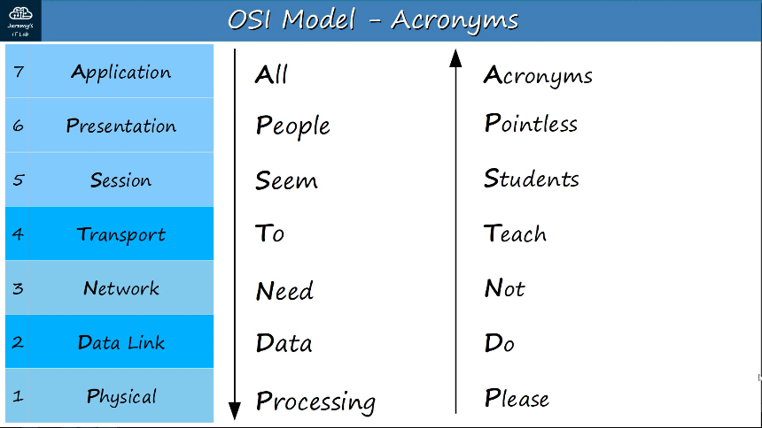
OSI Model
- “Open Systems Interconnection” model
- A conceptual model that categorizes and standardizes the different functions in a network.
- Created by the “Internation Organization for Standardization” (ISO)
- Functions are divided into 7 “Layers”
- These layers work together to mae the network work.
Layer 7, Application Layer
- This layer is closest to the end user.
- Interacts with software applications, for example your web browser (Brave, Firefox, Chrome, etc)
- HTTP and HTTPS are Layer 7 protocols
- Functions of Layer 7 include:
- Identifying communication partners
- Synchronizing communication
Layer 6, Presentation Layer
- Data in the application layer is in ‘application format’
- It needs to be ‘translated’ to a different format to be sent over the network
- The Presentation Layer’s job is to translate between application and network formats.
- For example, encryption of data as it is sent, and decryption of data as it is received.
- Also translates between different Application-Layer formats.
Layer 5, Session Layer
- Controls dialogues (sessions) between communicating hosts.
- Establishes, manages, and terminates connections between the local application (for example, your web browser) and the remote application (for example, YouTube)
OSI Model - The Upper Layers (Layer 7, 6, 5)
- Network engeineers don’t usually work with the top 3 layers.
- Application developers work with the top layers of the OSI model to connect their applications over networks.
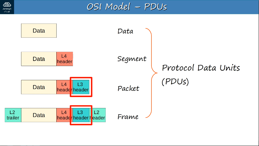
Layer 4, Transport Layer
- Segments and reassembles data for communications between end hosts
- Breaks large pieces of data into smaller segments which can be more easily sent over the network and are less likely to cause transmission problems if errors occur
- Provides host-to-host communication
- uses layer 4 header (data + L4 header = segment)
Layer 3, Network Layer
- Provides connectivity between end hosts on different networks (ie. outside of the LAN)
- Provides logical addressing (IP addresses)
- Provides path selection between source and destination
- Routers operate at Layer 3.
- Uses Layer 3 header (data + L4 header + L3 header = packet)
Layer 2, Data Link Layer
- Provides node-to-node connectivity and data transfer (for example, PC to switch, switch to router, router to router)
- Defines how data is formatted for transmission over a physical medium (for example, copper UTP cables)
- Detects and (possibly) corrects Physical Layer errors
- Uses Layer 2 addressing, seperate from Layer 3 addressing.
- Switches operate at Layer 2.
- Uses L2 trailer and header (L2 trailer + Data + L4 header + L3 header + L2 header = frame)
Layer 1, Physical Layer
- Defines physical characteristics of the medium used to transfer data between devices.
- For example, voltage levels, maximum transmission distances, physical connectors, cable specifications, etc.
- Digital bits are converted into electrical (for wired connections) or radio (for wireless connections) signals.
- All of the information in regarding cables, pin layouts, etc. is related to the Physical Layer.
Encapsulation - data moving from Layer 7 to Layer 1, the process of adding additional information when data is traveling in OSI or TCP/IP model. The additional information is added on the sender’s side, starting from Application layer to Physical layer.
De-encapsulation - data moving from Layer 1 to 7, the process in which information added through the encapsulation process is removed. The additional information is removed (de-encapsulated) on the receiver’s side, starting from the Physical layer to the Application layer.
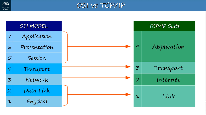
TCP/IP Suite
- Conceptual model and set of communications protocols used in the Internet and other networks
- Known as TCP/IP because those are two of the foundational protocols in the suite.
- Developed by the United State Department of Defense through DARPA (Defense Advanced Research Projects Agency)
- Similar structure to the OSI Model, but with fewer layers.
- This is the model actually in use in modern networks.
- The OSI model still influences how network engineers think and talk about networks.
1.1 Explain the role and function of network components
1.1.a Routers
Routers provide connectivity between LANs (Local Area Networks), and are therefore used to send data over the Internet.
1.1.b Layer 2 and Layer 3 switches
Switches provide connectivity to hosts within the same LAN. Switches typically have many more network interfaces/ports for end hosts to connect to (usually 24+).
Layer 3 switches, also known as Multilayer switches, are capable of both switching AND routing.
Layer 3 switches can have IP addresses assigned to its interfaces, like a router.
You can also create virtual interfaces, or SVIs (switch virtual interfaces), for each VLAN, and assign IP addresses to those interfaces.
These SVIs are used as the gateway address for each PC, instead of a router.
To send traffic to different subnets/VLANs, the PCs will send traffic to the switch, and the switch will route the traffic.
Routes can be configured on Layer 3 switches, and it can be used for inter-VLAN routing.
1.1.c Next-generation firewalls and IPS
Firewalls monitor and control network traffic based on configured rules. They are known as “Next-Generation Firewalls” when they include more modern and advanced filtering capabilities.
Network firewalls are hardware devices that filter traffic between networks.
Host-based firewalls are software applications that filter traffic entering and exiting a host machine, like a PC.
1.1.d Access points
An access point serves as the connection point between wireless and wired networks or as the center point of a stand-alone wireless network. In large installations, wireless users within the radio range of an access point can roam throughout a facility while maintaining seamless, uninterrupted access to the network.
1.1.e Controllers (Cisco DNA Center and WLC)
A network controller is a software that orchestrates network functions. It serves as an intermediary between the business and the network infrastructure. The organization enters their desired business objectives into the controller which in turn sets up the network to deliver on those objectives. Network controllers do their jobs by:
- Maintaining an inventory of devices in the network and their status
- Automating device operations such as configurations and image updates
- Analyzing network operations, identifying potential issues, and suggesting remediations
- Providing a platform for integration with other applications such as reporting systems
Cisco DNA Center is a central Management and Automation software, an application, that is used as a Controller for Cisco DNA. It is used as a management platform for both SD Access, Intent-Based Networks and existing traditional networks.
A wireless LAN controller (WLC) is a network component that manages wireless network access points and allows wireless devices to connect to the network.
1.1.f Endpoints/End hosts
An endpoint is a remote computing device that communicates back and forth with a network, examples include computers, laptops, mobile phones, tablets, and servers.
1.1.g Servers
A server is a device that provides functions or services for clients/endpoints on a network.
1.1.h PoE
PoE (Power over Ethernet) allows Power Sourcing Equipment (PSE) to provide power to Powered Devices (PD) over an Ethernet cable.
Typically the PSE is a switch and the PDs are IP phones, IP cameras, wireless access points, etc.
The PSE receives AC power from the outlet, converts it to DC power, and supplies that DC power to the PDs.
PoE has a process to determine if a connected devices needs power, and how much power it needs, as too much current can damage devices.
1.2 Describe characteristics of network topology architectures
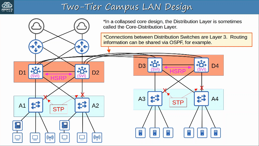
1.2.a 2-tier
The two-tier LAN design consists of two hierarchical layers:
- Access Layer
- Distribution Layer
Also called a ‘Collapsed Core’ design because it omits a layer that is found in the 3-Tier design: the Core Layer. The core in distribution layers are combined together in a single layer. The collapsed core in a two-tier network design provides physical and logical paths as well as a Layer 2 aggregation and demarcation point. In addition, a collapse core defines routing polices and network access policies and provides intelligent network services.
Access Layer:
- the layer that end hosts connect to (PCs, printers cameras, etc.)
- typically Access Layer Switches have lots of ports for end hosts to connect to
- QoS marking is typically done here
- Security sevices like port security, DAI, etc are typically performed here
- switchports might be PoE-enabled for wireless APs, IP phones, etc.
Distribution Layer (sometimes called Aggregation Layer):
- aggregates connections from the Access Layer Switches
- typically is the border between Layer 2 and Layer 3
- connects to services such as Internet, WAN, etc.
Two-tier Campus LAN Design:
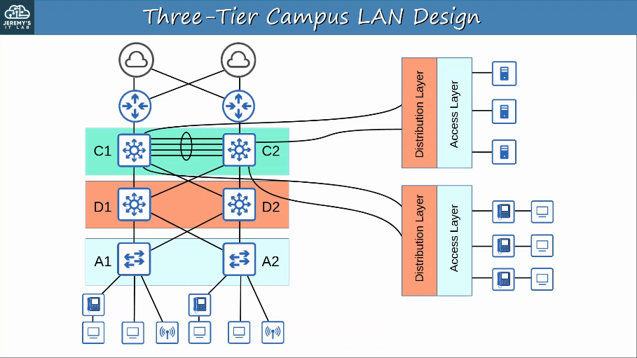
1.2.b 3-tier
In large LAN networks with many Distribution Layer switches (for example in separate buildings), the number of connections required between Distribution Layer switches grows rapidly.
To help scale large LAN networks, you can add a Core Layer. Cisco recommends adding a Core Layer if there are more than three Distribution Layers in a single location.
The three-tier LAN design consists of three hierarchical layers:
- Access Layer
- Distribution Layer
- Core Layer
Core Layer:
- Connects Distribution Layers together in large LAN networks
- The focus is speed (‘fast transport’)
- CPU-intensive operations such as security, QoS marking/classification, etc. should be avoided at this Layer
- Connections are all Layer 3. No spanning-tree!
- Should maintain connectivity throughout the LAN even if devices fail
The distribution layer provides route filtering and interVLAN routing. The distribution layer serves as an aggregation point for access layer network links.
Because the distribution layer is the intermediary between the access layer and the core layer, the distribution layer is the ideal place to enforce security policies, to provide QoS, and to perform tasks that involve packet manipulation, such as routing. Summarization and next-hop redundancy are also performed in the distribution layer.
The access layer serves as a media termination point for endpoints such as servers and hosts. Because access layer devices provide access to the network, the access layer is the ideal place to perform user authentication.
Three-Tier Campus LAN Design:
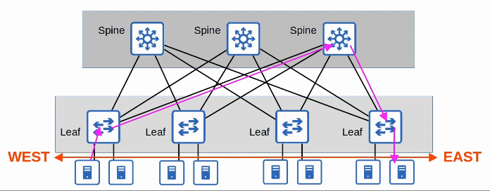
1.2.c Spine-leaf
Data centers are dedicated spaces/buildings used to store computer systems such as servers and network devices.
Traditional data center designs used a three-tier architecture (Access-Distribution-Core) shown previously.
This worked well when most traffic in the data center was North-South.
With the precedence of virtual servers, applications are often deployed in a distributed manner (across multiple physical servers), which increases the amount of East-West traffic in the data center.
The traditional three-tier architecture led to bottlenecks in bandwidth as well as variablility in the server-to-server latency depending on the path the traffic takes.
To solves this, Spine-Lead architecture (also called Clos architecture) has become prominent in data centers.
There are some rules about Spine-Leaf architecture:
- Every Leaf switch is connected to every Spine switch
- Every Spine switch is connected to every Leaf switch
- Leaf switches do not connect to other Leaf switches
- Spine switches do not connect to other Spine switches
- End hosts (servers etc.) only connect to Leaf switches
The path taken by traffic is randomly chosen to balance the traffic load among the Spine switches
Each server is separated by the same number of ‘hops’ (except those connected to the same Leaf), providing consistent latency for East-West traffic.
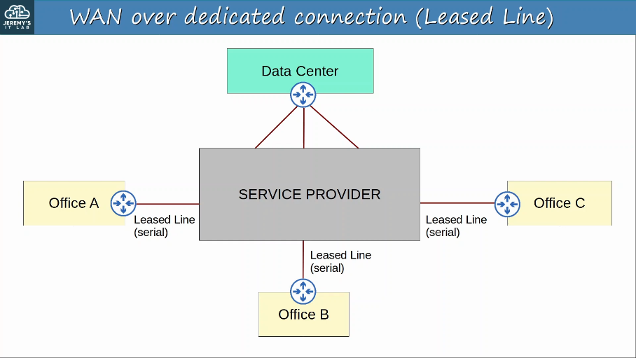
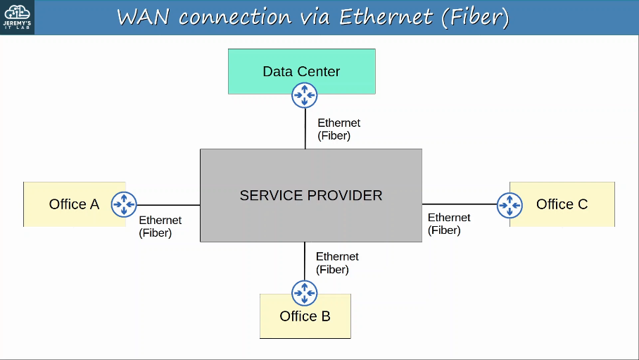
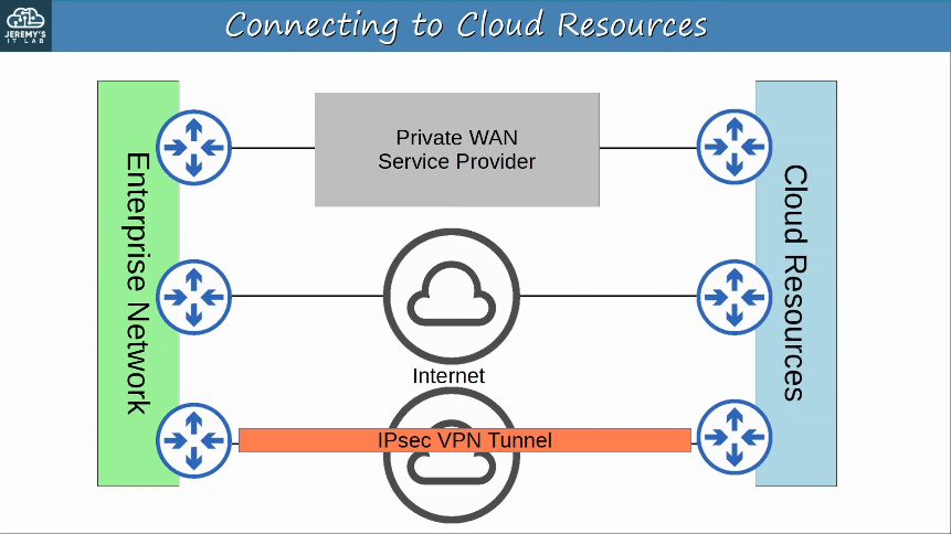
1.2.d WAN
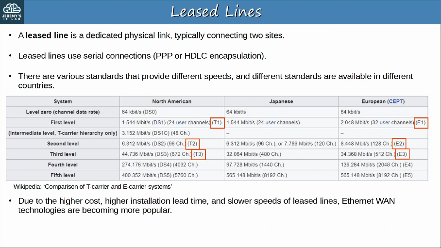
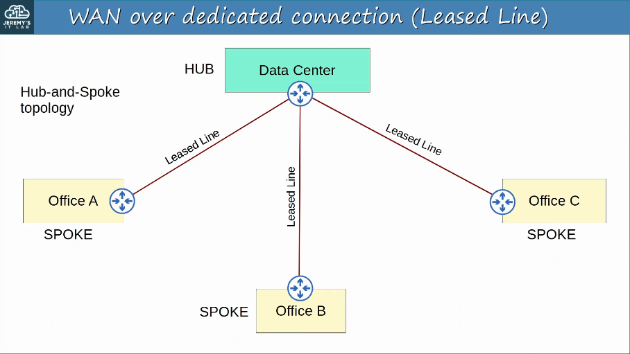
WAN (Wider Area Network) is a network that extends over a large geographic area.
WANs are used to connect geographically seperate LANs.
Although the Internet itself can be considered a WAN, the term WAN is typically used to refer to an enterprise’s private connections that connect their offices, data centers, and other sites together.
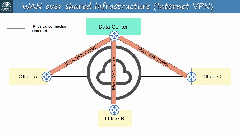
Over public/shared networks like the Internet, VPNs (Virtual Private Networks) can be used to create private WAN connections.
There have been many different WAN technologies over the years. Depending on the location, some will be available and some will not be.
Technologies which are considered ‘legacy’ (old) in one country might still be used in other countries.
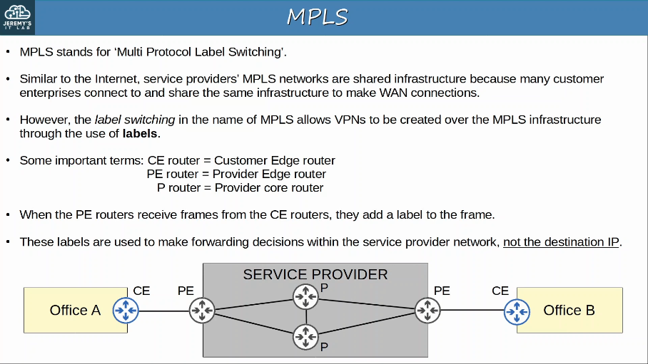
Private WAN services such as leased lines and MPLS provide security because each customer’s traffic is seperated by using dedicated physical connections (leased line) or by MPLS tags.
WAN Architectures:
To provide secure communications over the Internet, VPNs (Virtual Private Networks) are used.
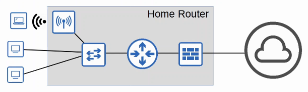
1.2.e Small office/home office (SOHO)
SOHO (Small Office/Home Office) refers to the office of a small company, or a small home office with few devices.
- Doesn’t have to be an actual home ‘office’, if your home has a network connected to the Internet it is considered a SOHO network.
SOHO devices don’t have complex needs, so all networking functions are typically provided by a single device, often called a ‘home router’ or ‘wireless router’
This one device can serve as a:
- Router
- Switch
- Firewall
- Wireless Access Point
- Modem
1.2.f On-premise and cloud
Traditional IT infrastructure deployments were some combination of the following:
On-Premises
- All servers, network devices, and other infrastructure are located on company property.
- All equipment is purchased and owned by the company using it.
- The company is responsible for the necessary space, power, and cooling.
Colocation
- Data centers that rent out space for customers to put their infrastructure (servers, network devices)
- The data center provides the space, electricity, and cooling.
- The servers, network devices, etc are still the responsibility of the end customer, although they are not located on the customer’s premises.
Cloud service provide an alternative that is hugely popular, and continuing to grow.
Most people associate ‘cloud’ with public cloud providers such as AWS, Microsoft Azure, GCP
- Although this is the most common use of cloud services, it’s not the only one.
Cloud computing is defined by the American NIST in SP 800-145 as follows.
The five essential characteristics of cloud computing are:
- On-demand self-service
- A consumer can unilaterally provision computing capabilities, such as server time and network storage, as needed automatically without requiring human interaction with each service provider.
- The customer is able to use the service (or stop using the service) freely (via a web portal) without direct communication to the service provider.
- Broad network access
- Capabilities are available over the network and accessed through standard mechanisms that promote use by hereogeneous thin or thick client platforms (e.g mobile phones, tablets, laptops, and workstations).
- The service is available through standard network connections (ie, the Internet or private WAN connections), and can be accessed through many kinds of devices.
- Resource pooling
- A pool of resources is provided by the service provider, and when a customer requests a service (for example creates a new VM), the resources to fulfill that request are allocated from the shared pool.
- Rapid elasticity
- Customers can quickly expand the services they use in the cloud (for example, add new VMs, expand storage, etc) from a pool of resources that appears to be infinite. Likewise, they can quickly reduce their services when not needed.
- Measured service
- The cloud service provider measures the customer’s usage of cloud resources, and the customer can measure their own use as well. Customers are charged based on usage (for example, X dollars per gigabyte of storage per day).
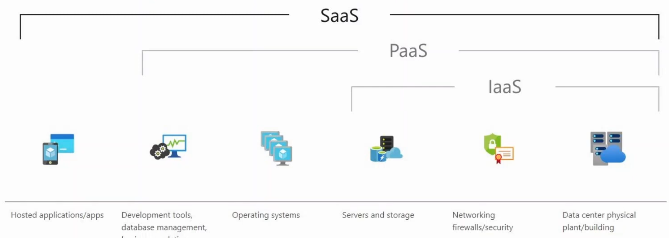
The three service models of cloud:
- Software as a Service (SaaS)
- The capability provided to the consumer is to use the provider’s applications running on a cloud infrastructure. The application are accessible from various client devices through either a thing client interface, such as a web browser (e.g. web-based email), or a program interface.
- The consumer does not manage or control the underlying cloud infrastructure including network, servers, operating systems, storage, or even individual application capabilities, with the possible exception of limited user-specific application configuration settings. ex. Microsoft Office 365
- Platform as a Service (PaaS)
- The capability provided to the consumer is to deploy onto the cloud infrastructure consumer-created or acquired applications creating using programming languages, libraries, services, and tools supported by the provider.
- The consumer does not manage or control the underlying cloud infrastructure including network, servers, operating systems, or storage, but has control over the deployed applications and possibly configuration settings for the application-hosting environment. ex. AWS Lambda and Google App Engine.
- Infrastructure as a Service (IaaS)
- The capability provided to the consumer is to provision processing, storage, networks, and other fundamental computing resources where the consumer is able to deploy and run arbitrary software, which can include operating systems and applications.
- The consumer does not manage or control the underlying cloud infrastrcture but has control over operating systems, storage, and deployed applications; and possibly limited control of select networking components (e.g. host firewalls).
- Examples include Amazon EC2 and Google Compute Engine.
The four deployment models of cloud:
- Most people assume that ‘cloud’ means public cloud providers such as AWS, Azure, and GCP.
- Although ‘Public cloud’ is the most common deployment model, it’s not the only one.
The four deployment models of cloud computing are:
- Private cloud
- The cloud infrastructure is provisioned for exclusive use by a single organization comprising multiple consumers (e.g. business units). It may be owned, managed, and operated by the organization, a third party, or some combination of them, and it may exist on or off premises.
- Private clouds are generally only used by large enterprises.
- Although the cloud is private, it may be owned by a third party.
- For example, AWS provides private cloud services for the American DoD.
- Private clouds may be on or off premises.
- Many people assume that ‘cloud’ and ‘on-prem’ are two different things, but that is not always the case.
- The same kinds of services offered are the same as in public clouds (Saas, PaaS, IaaS), but the infrastructure is reserved for a single organization
- Community cloud
- The cloud infrastructure is provisioned for exclusive use by a specific community of consumers from organizations that have shared concerns (e.g. mission, security requirements, policy, and compliance considerations). It may be owned, managed, and operated by one or more of the organizations in the community, a third party, or some combination of them, and it may exist on or off premises.
- This is the least common cloud deployment.
- Similar to private cloud, but the infrastructure is reserved for use by only a specific group of organizations.
- Public cloud
- The cloud infrastructure is provisioned for open use by the general public. It may be owned, managed, and operated by a business, academic, or government organization, or some combination of them. It exists on the premises of the cloud provider.
- This is the most common cloud deployment.
- Popular public cloud service providers include:
- AWS (Amazon Web Services)
- Microsoft Azure
- GCP (Google Cloud Platform)
- OCI (Oracle Cloud Infrastructure)
- IBM Cloud
- Alibaba Cloud
- Hybrid cloud
- The cloud infrastructure is a composition of two or more distinct cloud infrastrctures (private, community, or public) that remain unique entities, but are bound together by standardized or proprietary technology that enables data and application portability (e.g. cloud bursting for load balancing between clouds).
- This is basically any combination of the previous three deployment types.
- For example, a private cloud which can offload to a public cloud when necessary.
Benefits of Cloud Compouting
- Cost
- CapEx (Capital Expenses) of buying hardware and software, setting up data centers etc. are reduced or eliminated.
- Global Scale
- Cloud services can scale globally at a rapid pace. Services can be set up and offered to customers from a geographic location close to them.
- Speed/Agility
- Services are provided on demand, and vast amounts of resources can be provisioned within minutes.
- Productivity
- Cloud services remove the need for many time-consuming tasks such as procuring physical servers, racking them, cabling, installing and updating operating systems, etc.
- Reliability
- Backups in the cloud are very easy to perform. Data can be mirrored at multiple sites in different geographic locations to support disaster recovery.
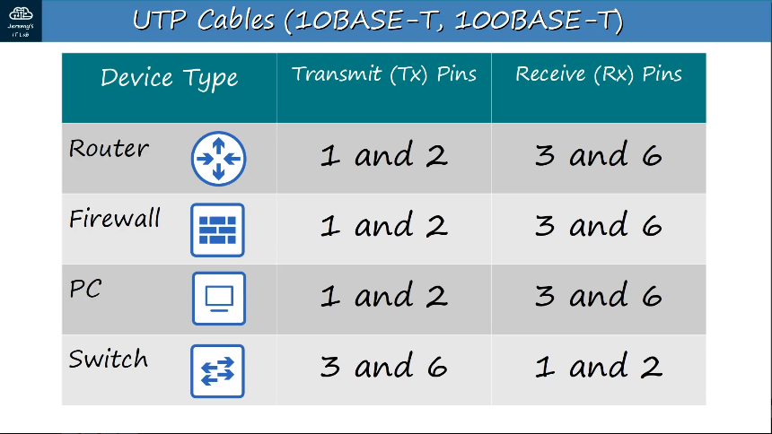
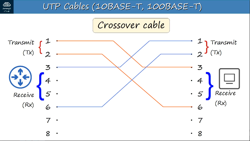
1.3 Compare physical interface and cabling types
RJ-45 (RJ = Registered Jack) - Standard connector for copper UTP cables that has 8 pin connections.
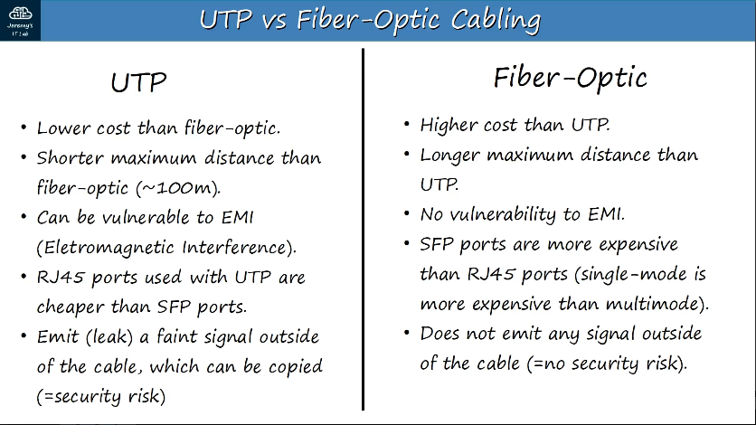
UTP cables - Unshielded twisted pair copper wire, contains 4 pairs of wires twisted together, with 8 wires in total.
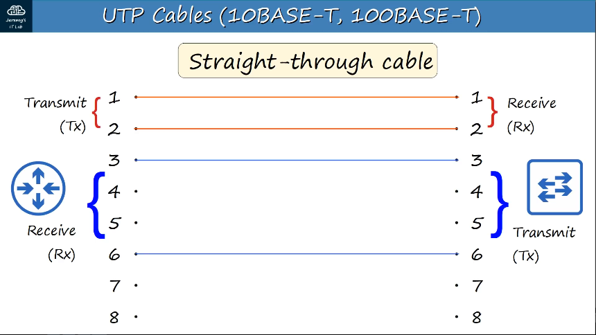
Straight-through cable -
 Crossover cable -
 1000BASE-T, 10GBASE-T cabling -
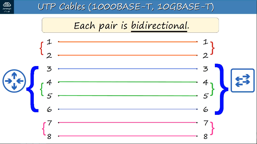
Using Auto MDI-X, devices are able to automatically detect which pins their neighbor is using to transmit data and automatically adjust their pins to receive and transmit on the correct pins.
Infrastructure:
T1 connections use the copper wire infrastructure of the public switched network (PSTN) to provide a maximum throughput of 1.544 Mbps.
To achieve the 1.544-Mbps rate, T1 connections encapsulate data in DS1 siggnaling frames. DS1 signaling frames use 24 DS0 channels and one framing bit. Each of the 24 DS0 channels transfers eight bits of data at a time. The inclusion of the framing bit raises the total amount of data in a single DS1 frame to 193 bits. T1 connections transmit 8000 DS1 frames per second, which brings the total throughput to 1.544 Mbps.
T1 connections typically transfer data across two pairs of shielded copper wires, which extend from he service provider to the customer. One pair of wires within the T1 line is used to send data, and the other pair is used to receive data.
Cable connections use a coaxial line from the service provider to the customer to provide Internet access. Originally, cable providers offered only television service. Providers realizedd tha coaxial lines offered enough bandwidth to support simultaneous television and Internet service.
However, before cable providers could start offering Internet service, they had to redesign their infrastructure to allow for two-way communications. One of the infrastructure changes was the introduction of the cable modem.
Cable modems are used to convert an analog signal from the provider into a digital signal that can be used by a computer and vice versa. Cable modems provide speeds of up to 27 Mbps, making cable one of the fastest options for home Internet service.
Digital Subscriber Line (DSL) uses the copper wire infrastructure of the PSTN (Public Switched Telephone Network). However, DSL solutions can provide a maximum throughput hat is higher than 1.544 Mbps. Filters must be installed on each telephone outlet in order to segregate a DSL Internet signal and a telephone voice signal.
In order to receive DSL service, the subscribers must have a DSL modem installed at their home or office. The DSL modem is used to convert signals originating from a computer into a frequency that can be transmitted over the DSL line without interfering with other types of transmissions.
DSL upload speeds are typically slower than DSL download speeds. DSL service is available in a variety of forms including Asynchronous DSL (ADSL), Synchronous DSL (SDSL), and Very-high-data-rate DSL (VDSL).
Satellite-based Internet service downloads are received wirelessly through the use of a dish antenna. Satellite Internet service is typically slower than cable, DSL, or T1 connections. In addition, because satellite transmissions do not transmit over a physical medium, they are highly susceptible to latency and interference. However, satellite is a long-distance option for areas where the necessary infrastructure for other types of Internet service is absent, such as rural areas.
Cellular Internet service has become a less expensive alternative for some in rural areas who are capable of receiving 3G, 4G, or 4G LTE signals. In addition, celllar Internet is a common means of Internet access for people who travel frequently.
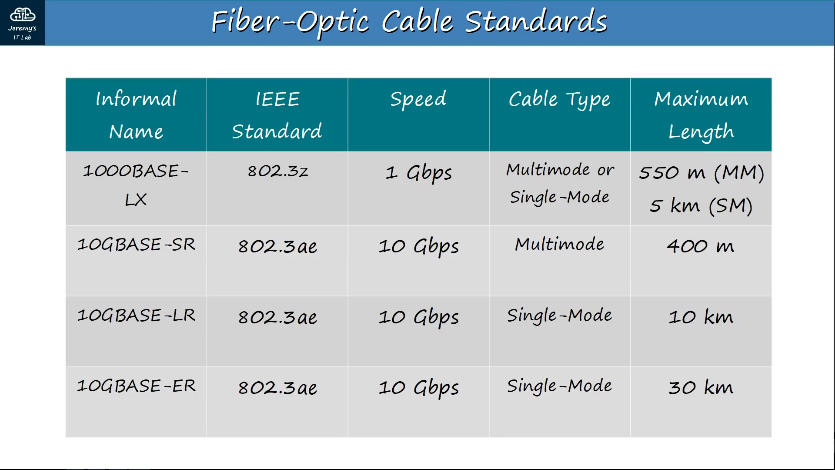
1.3.a Single-mode fiber, multimode fiber, copper
SFP Transceiver (SFP = Small Form-Factor Pluggable) - connector used for fiber-optic ports on a switch, connects to Fiber-Optic cabling.
Single-mode fiber is narrower than multimode fiber, light enters at a single angle (mode) from a laser-based transmitter. Allows for longer cables than both UTP and multimode fiber, but also more expensive.
Multimode fiber is wider than single-mode fiber, allows multiple angles (modes) of light waves to enter the fiberglass core. Allows longer cables than UTP, but shorter than single-mode fiber.
Shared or broadcast Channel:
- All computers connected to a shared broadcast-based communication channel and share the channel bandwidth.
- Security issues as a result of broadcasting to all computers.
- Cost effective due to reduced number of channels and interface hardware components.
Point-to-point
- Computers connected by communication channels that each connect exactly two computers with access to full channel bandwidth.
- Forms a mesh or point-to-point network
- Allows flexibility in communication hardware, packet formats, etc.
- Provides security and privacy because communication channel is not shared.
- Number of channels grows as square of number of computers
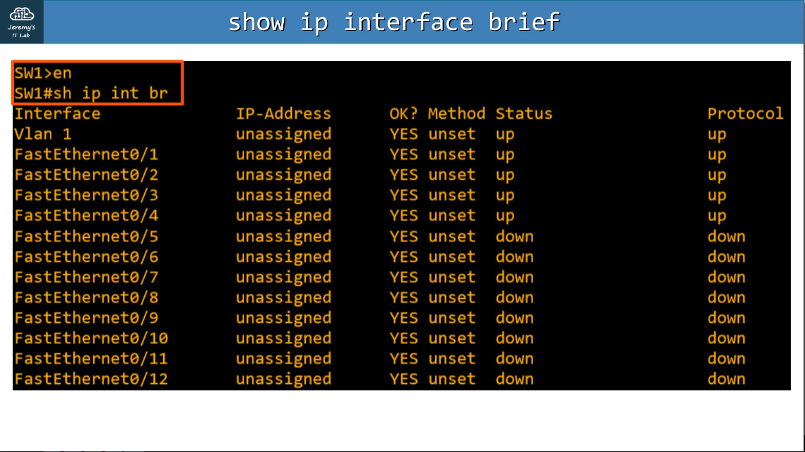
1.4 Identify interface and cable issues (collisions, errors, mismatch duplex, and/or speed)
show ip interface brief
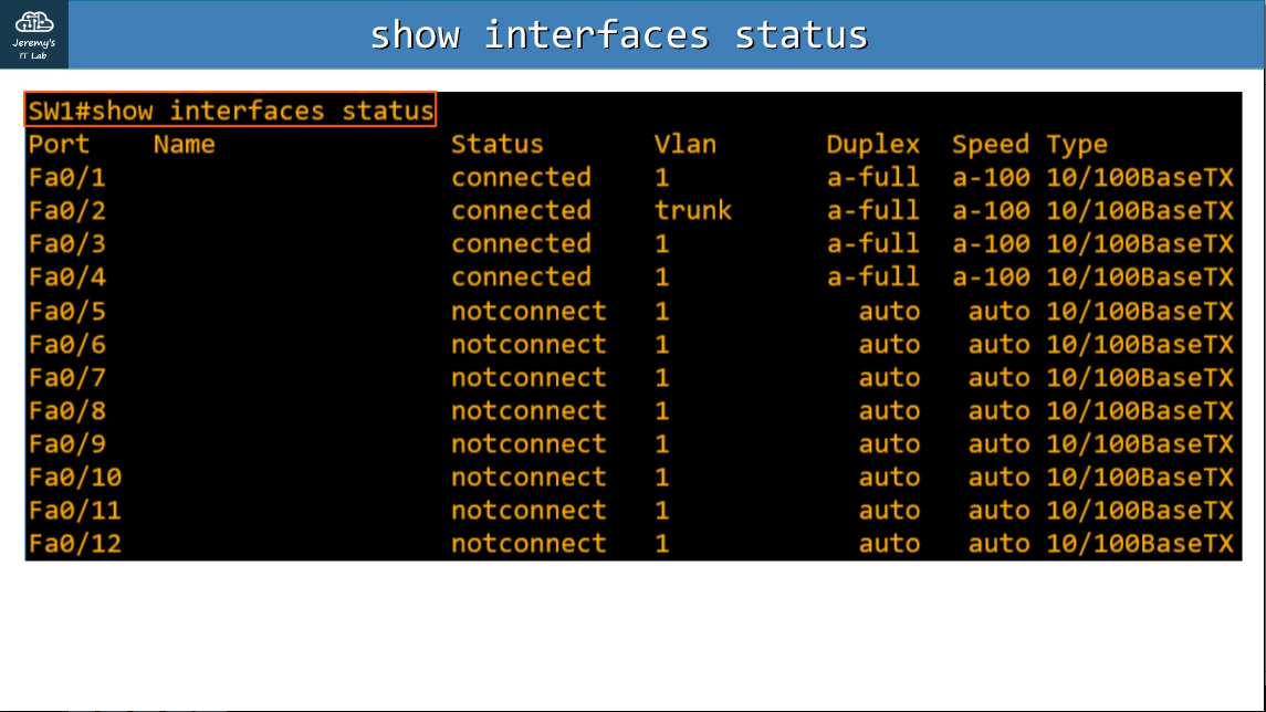
show interfaces status
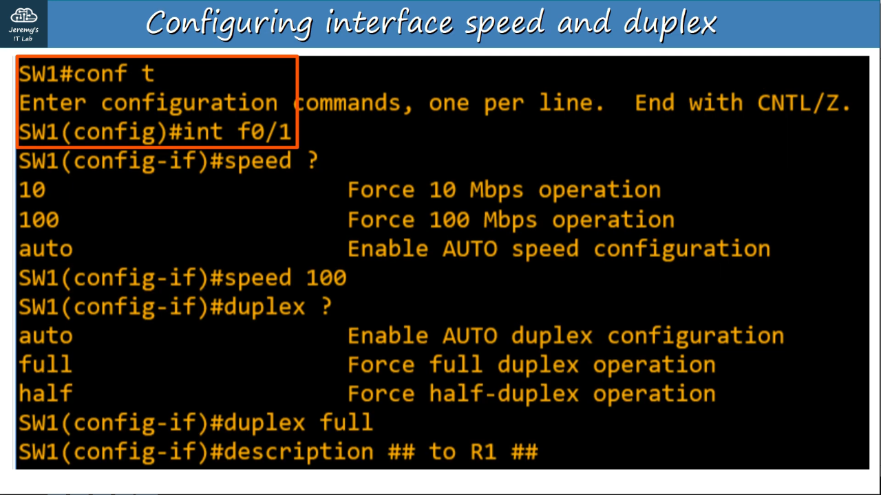
Configuring interfaces speed/duplex:
CSMA/CD (Carrier Sense Multiple Access with Collision Detection)
- Before sending frames, devices ‘listen’ to the collision domain until they detect that other devices are not sending.
- If a collision does occur, the device sends a jamming signal to inform the other devices that a collision happened.
- Each device will wait a random period of time before sending frames again.
- The process then repeats.
- Typically only an issue in networks that use hubs (which are mostly obsolete today)
- Switches operate in full duplex, rather than half duplex like hubs.
Speed/Duplex Autonegotiation
- Interfaces that can run at different speed (10/100 or 10/100/1000) have default settings of speed auto and duplex auto.
- Interfaces ‘advertise’ their capabilities to the neighboring device, and they negotiate the best speed and duplex settings they are both capable of.
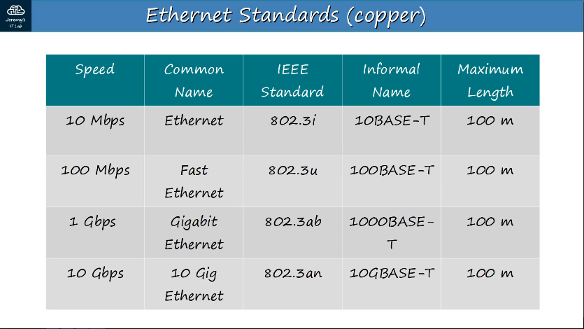
Ethernet - 10 Mbps
FastEthernet - 10/100 Mbps
GigabitEthernet - 10/100/1000 megabits/second Mbps
What if autonegotiation is disabled on the device connected to the switch?
- Speed: The switch will try to sense the speed that the other device is operating at.
- If it failts to sense the speed, it will use the slowest supports speed (ie. 10 Mbps on a 10/100/1000 interface)
- Duplex: If the speed is 10 or 100 Mbps, the switch will use HALF duplex (BAD, will lead to misconfigurations). If the speed is 1000 Mbps or greater, use full duplex.
- To avoid misconfigurations, use autonegotiation on ALL devices in the network.
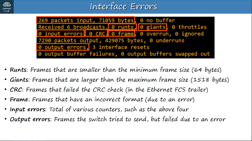
Interface errors can be viewed by using #show interfaces f0/#
Whhen using an SFP transceiver and receiving a SYS-TRANSCEIVER_NOTAPPROVED error when booting a switch, it is likely that you have used a third-party SFP module that is not supported.
If you connected a cable to the wrong SFP module port, you would most likely notice that the ports on the switches are up, but the line protocol is down.
If the fiber cables are broken, you would notice that the port status LEDs on the SFP module are not lit.
If the SFP module is installed upside down, teh switch would not recognize the SFP module, and the output from the show commands would contain no information about the module.
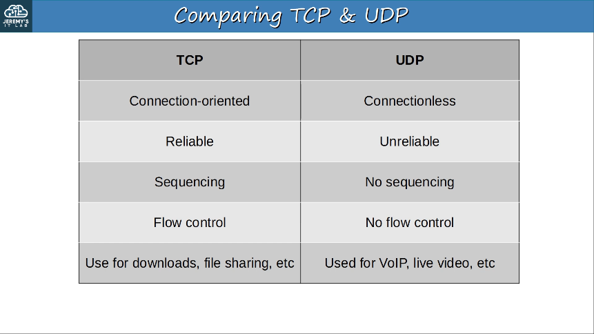
1.5 Compare TCP to UDP
TCP (Transmission Control Protocol)
- TCP is connection-oriented
- Before actually sending data to the destination host, the two hosts commmunicate to establish a connection.
- TCP provides reliable communication.
- The destination host must acknowledge that it received each TCP segment.
- If a segment isn’t acknowledged, it is sent again.
- TCP provides sequencing
- Sequence numbers in the TCP header allow destination hosts to put segments in the correct order even if they arrive out of order.
- TCP provides flow control
- The destination host can tell the source host to increase/decrease the rate that data is sent.
UDP (User Datagram Protocol)
- UDP is not connection-oriented
- The sending host does not establish a connection with the destination host before sending data. The data is simply sent.
- UDP does not provide reliable communication
- When UDP is used, acknowledgments are not sent for received segments. If a segment is lost, UDP has no mechanism to re-transmit it. Segments are sent “best-effort”.
- UDP does not provide sequencing.
- There is no sequence number field in the UDP header. If segments arrive out of order, UDP has no mechanism to put them back in order.
- UDP does not provide flow control
- UDP has no mechanism like TCP’s window size to control the flow of data.
Comparing TCP & UDP
- TCP provides more features than UDP, but at the cost of additional overhead.
- For applications that require reliable communications (for example downloading a file), TCP is preferred.
- For applications like real-time voice and video, UDP is preferred.
- There are some applications that use UDP, but provide reliability etc within the application itself.
- Some applications use both TCP & UDP, depending on the situation.
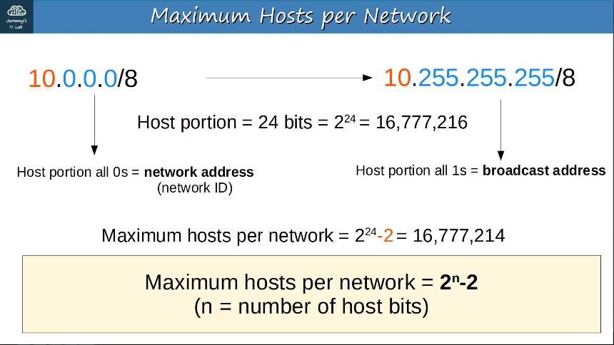
 Maximum number of hosts per network:
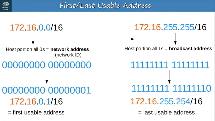
 First/Last Usable Address:
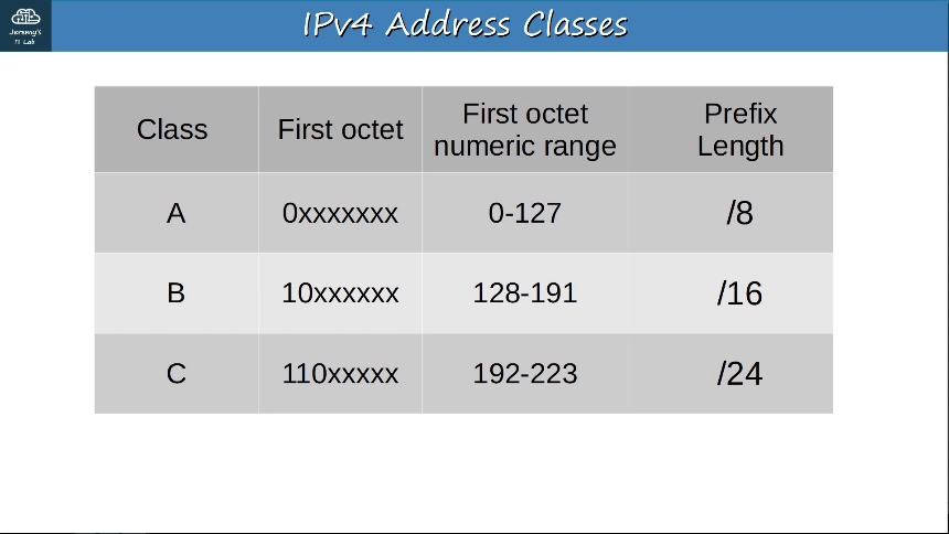
CIDR (Classless Inter-Domain Routing) removed the previous requirements of:
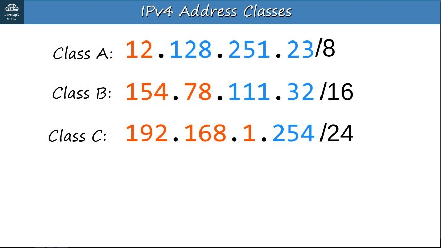
Class A = /8
Class B = /16
Class C = /24 This allows larger networks to be split into smaller networks, allowing greater efficiency. These smaller networks are called "subnetworks" or "subnets". 
Using VLSM (Variable-Length Subnet Masks) will allow the creation of subnets of different sizes, to make use of network addresses even more efficient.
1.7 Describe the need for private IPv4 addressing
IPv4 doesn’t provide enough addresses for all devices that need an IP address in the modern world. The long term solutionn is to switch to IPv6.
There are three main short-term solutions:
- CIDR
- Private IPv4 addresses
- NAT
Private IPv4 address ranges as defined in RFC 1918
- 10.0.0.0/8 (10.0.0.0 to 10.255.255.255) (Class A)
- 172.16.0.0/12 (172.16.0.0 to 172.31.255.255) (Class B)
- 192.168.0.0/16 (192.168.0.0 to 192.168.255.255) (Class C)
These addresses are free to be used in networks. They don’t have to be globally unique. Because private IPv4 addresses can’t be used over the Internet, so the PCs can’t access the Internet without NAT.
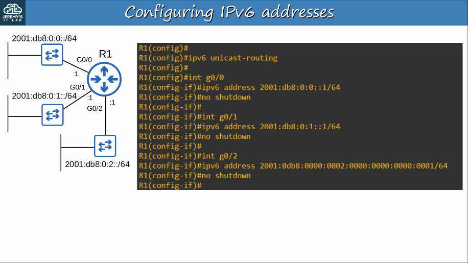
Configuring IPv6:
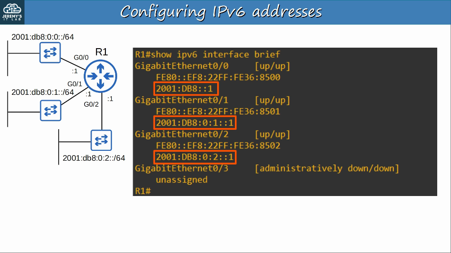
 Verify IPv6:
1.9 Describe IPv6 address types
An IPv6 address is 128 bits written in hexadecimal.
1.9.a Unicast (global, unique local, and link local)
Global unicast ipv6 addresses are public addresses which can be used over the Internet.
- Must register to be used. Because they are public addresses, it is expected that they are globally unique.
- Originally defined as 2000::/3 block, always beginning with 2 or 3 because the first 3 bits are always 001, now defined as all addresses which aren’t reserved for other purposes.
Unique local IPv6 addresses are private addresses which cannot be used over the Internet.
- Does not need to be registered. They can be used freely within internal networks and don’t need to be globablly unique. Can’t be routed over the Internet.
- Uses address block FC00::/8 and FD00::/8
Link-local IPv6 addresses are automatically generated on IPv6-enabled interfaces. Use command R1(config-if)#ipv6 enable on an interface to enable IPv6 on that interface
- Uses address block FE80:://10, specified in RFC 4291
- The interface ID is generated using EUI-64 rules.
- Link-local means that these addresses are used for communication within a single link (subnet). Routers will not route packets with a link-local destination IPv6 address.
- Common uses of link-local addresses:
- routing protocol peerings (OSPFv3 uses link-local addresses for neighbor adjacencies)
- next-hop addresses for static routes
- Neighbor Discovery Protocol (NDP, IPv6’s replacement for ARP) uses link-local addresses to function
1.9.b Anycast
Anycast is a new feature of IPv6.
Anycast is “one-to-one-of-many”
Multiple routers are configured with the same IPv6 address.
- They use a routing protocol to advertise the address.
- When hosts sends packets to that destination address, routers will forward it to the nearest router configured with that IP address (based on routing metric).
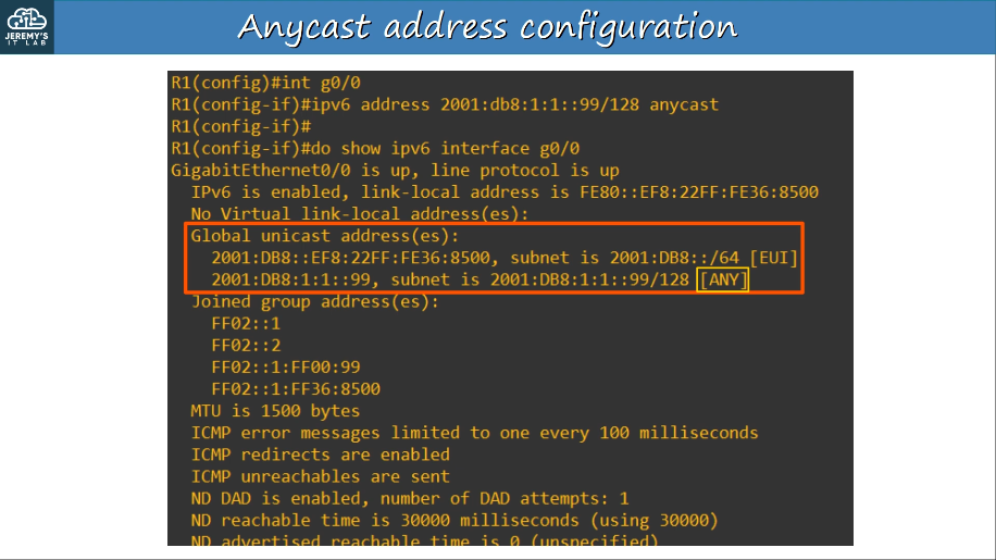
- There is no specific address range for anycast addresses. Use a regular unicast address (global unicast, unique local) and specify it as an anycast address:
- R1(config-if)# ipv6 address (ipv6 address)/128 anycast
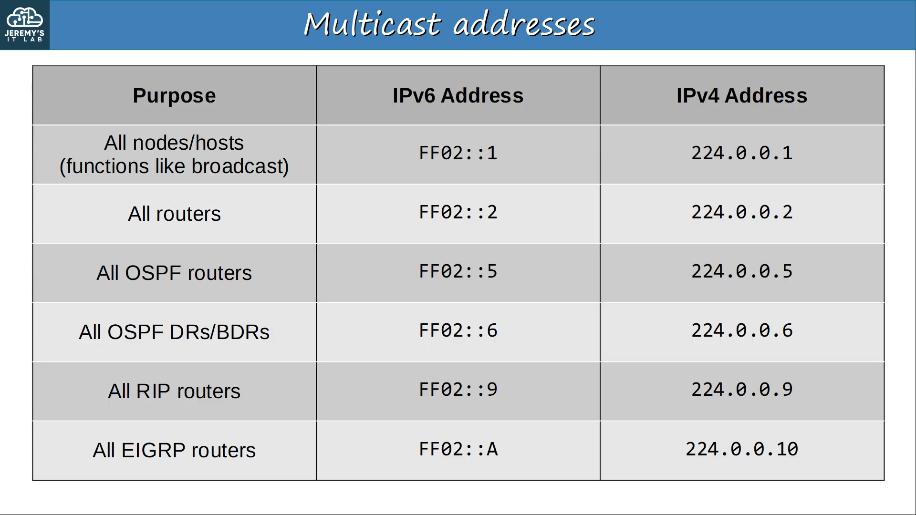
1.9.c Multicast
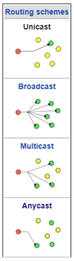
Unicast addresses are one-to-one
- one source to one destination
Broadcast addresses are one-to-all
- one source to all destinations (within the subnet).
Multicast addresses are one-to-many.
- one source to multiple destinations (that have joined the specific multicast group).
IPv6 uses range FF00::/8 for multicast.
IPv6 doesn’t use broadcast (there is no “broadcast address” in IPv6).
 Verify multicast addresses:
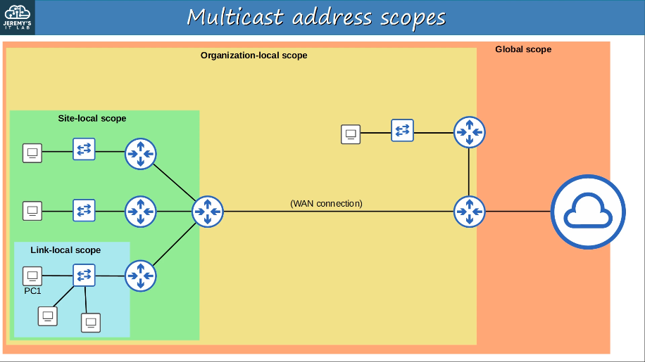
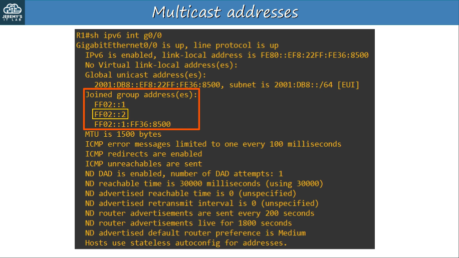 IPv6 defines multiple multicast “scopes” which indicate how far the packet should be forwarded. The addresses in the previous slide all use the “link-local” scope (FF02), which stays in the local subnet.
IPv6 multicast scopes:
IPv6 defines multiple multicast “scopes” which indicate how far the packet should be forwarded. The addresses in the previous slide all use the “link-local” scope (FF02), which stays in the local subnet.
IPv6 multicast scopes:
-
Interface-local (FF01): The packet doesn’t leave the local device. Can be used to send traffic to a service within the local device.
-
Link-local (FF02): The packet remains in the local subnet. Routers will not route the packet between subnets.
-
Site-local (FF05): The packet can be forwarded by routers. Should be limited to a single physical location (not forwarded over a WAN)
-
Organization-local (FF08): Wider in scope than site-local (an entire company/organization).
-
Global (FF0E): No boundaries. Possible to be routed over the Internet.
IPv6 hosts use the multicasting capabilities of the ND (Neighbor Discovery) protocol to discover the link layer addresses of neighbor hosts. The Hop Limit field is typicaly set to 255 in ND packets that are sent to neighbors. Routers decrement the Hop Limit value as a packet is forwarded from hop to hop.
Therefore, a router that receives an ND packet with a Hop Limit value of 255 considers the source of the ND packet to be a neigbhbor. If a router receives an ND packet with a Hop Limit value that is less than 255, the packet is ignored, therby protecting the router from threats that could result from the ND protocol’s lack of neighbor authentication.
Routing schemes:
1.9.d Modified EUI 64
EUI stands for Extended Unique Identifier
Modfied EUI-64 is a method of converting a MAC address (48 bits) into a 64-bit interface Identifier
This interface identifier can then become the “host portion” of a /64 IPv6 address.
To convert the MAC address:
- Split the MAC address into two halves
- Insert FFFE in the middle
- Invert the 7th bit
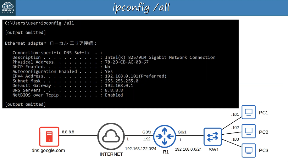
1.10 Verify IP parameters for Client OS (Windows, Mac OS, Linux)
ipconfig /all
1.11 Describe wireless principles
Wireless network have some issues that need to be dealt with.
- All devices within range receive all frames, like devices connected to an Ethernet hub.
- Privacy of data within the LAN is a greater concern.
- CSMA/CA (Carrier Sense Multiple Access with Collision Avoidance) is used to facilitate half-duplex communications.
- Wireless communications are regulated by various international and national bodies.
- Wireless signal coverage area must be considered.
- Signal range, absorption, reflection, refraction, diffraction, and scattering.
- Other devices using the same channels can cause interference.
- For example, a wireless LAN in your neighbor’s house/apartment.
1.11.a Nonoverlapping Wi-Fi channels
In a small wireless LAN with only a single AP (Access Point), you can use any channel.
However, in larger WLANs with multiple APs, it’s important that adjacent APs don’t use overlapping channels. This helps avoid interference.
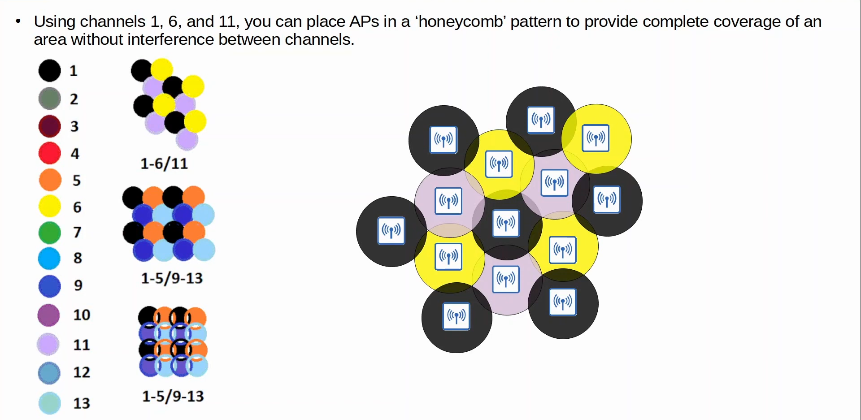
In the 2.4 GHz band, it is recommended to use channels 1, 6, and 11.
Using channels 1,6 and 11, you can place AP’s in a ‘honeycomb’ pattern to provide complete coverage of an area without interference between channels.
1.11.b SSID
802.11 defines different kinds of service sets which are groups of wireless network devices.
There are three main types:
- Independent
- An IBSS (Independent Basic Service Set) is a wireless network in which two or more wireless devices connect directly without using an AP (Access Point)
- Also called an ad hoc network
- Can be used for file transfer (ie. Airdrop)
- Not scalable beyond a few devices
- Infrastructure
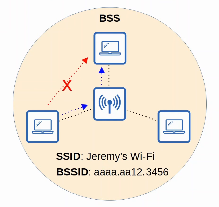
- A BSS (Basic Service Set) is a kind of Infrastructure Service Set in which clients connect to each other via an AP (Access Point), but not directly to each other.
- A BSSID (Basic Service Set ID) is used to uniquely identify the AP.
- Other APs can use the same SSID, but not the same BSSID
- The BSSID is the MAC address of the AP’s radio
- Wireless devices request associate with the BSS.
- Wireless devices that have asociated with the BSS are called ‘cients’ or ‘stations’.
- The area around an AP where its signal is usable is called a BSA (Basic Service Area)
- Clients must communicate via the AP, not directly with each other.
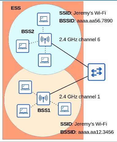
- To create large wireless LANs beyond the range of a single AP, we use an ESS (Extended Service Set).
- APs with their own BSSs are connected by a wired network.
- Each BSS uses the same SSID.
- Each BSS has a unique BSSID.
- Each BSS uses a different channel to avoid interference.
- Clients can pass between APs without having to reconnect, providing a seamless Wi-Fi experience when moving between APs.
- The BSAS should overlap about 10-15%.
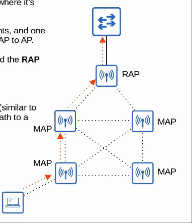
- Mesh
- An MBSS (Mesh Basic Service Set) can be used in situations where it’s difficult to run an Ethernet connection to every AP.
- Mesh APs use two radios: one to provide a BSS to wireless clients, and one to form a ‘backhaul network’ which is used to bridge traffic from AP to AP.
- At least one AP is connected to the wired network, and it is called the RAP (Root Access Point)
- The other APs are called MAPs (Mesh Access Points)
- A protocol is used to determine the best path through the mesh (similar to how dynamic routing protocols are used to determine the best path to a destination.
All devices in a service set share the same SSID (service set identifier)
The SSID is a human-readable name which identifies the service set. (spaghetti and meatballs)
The SSID does NOT have to be unique.
Most wireless networks aren’t standalone networks.
- Rather, they are a way for wireless clients to connect to the wired network infrastructure.
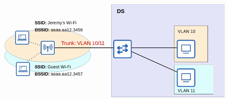
- In 802.11, the upstream wired network is called the DS (Distribution System)
- Each wireless BSS or ESS is mapped to a VLAN in the wired network.
- It’s possible for an AP to provide multiple wireless LANs, each with a unique SSID.
- Each WLAN is mapped to a separate VLAN and connected to the wired network via a trunk.
- Each WLAN uses a unique BSSID, usually by incrementing the last digit of the BSSID by one.
1.11.c RF
Wi-Fi uses two main bands (frequency ranges).
- 2.4 GHz band
- The actual range is 2.400 GHz to 2.4835 GHz
- 5 GHz band
- The actual range is from 5.150 GHz to 5.825 GHz
- Divided into four smaller bands:
- 5.150 GHz to 5.250 GHz
- 5.250 GHz to 5.350 GHz
- 5.470 GHz to 5.725 GHz
- 5.725 GHz to 5.825 GHz
The 2.4 GHz band typically provides further reach in open space and better penetration of obstacles such as walls.
- However, more devices tend to use the 2.4 GHz band so interference can be a bigger problem compared to the 5 GHz band.
Each band is divided up into multiple ‘channels’.
- Devices are configured to transmit and receive traffic on one (or more) of these channels.
The 2.4 GHz band is divided into several channels, each with a 22 MHz range.
1.11.d Encryption
Although security is important in all networks, it is even more essential in wireless networks.
Because wireless signals are not contained within a wire, any device within range of the signal can receive the traffic.
In wire networks traffic is often only encrypted when sent over an untrusted network such as the Internet.
In wireless networks, it is very important to encrypt traffic sent between the wireless clients and the AP.
There are many possible protocols that can be used to encrypt traffic.
All devices on the WLAN will use the same protocol, however each client will use a unique encryption/decryption key so that other device can’t read its traffic.
A ‘group key’ is used by the AP to encrypt traffic that it wants to send to all of tis clients.
- All of the clients associated with the AP keep that key so they can decrypt the traffic.
A MIC (Message Integrity Check) is added to messages to help protect their integrity.
Authentication methods:
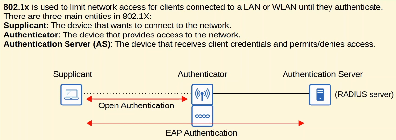
- Open Authentication
- The client sends an authentication request, and the AP accepts it. No questions asked.
- This is clearly not a secure authentication method
- After the client is authenticated and associated with teh AP, it’s possible to require the user to authenticate via other methods before access to the network is granted (ie. Starbucks Wifi)
- WEP (Wired Equivalent Privacy)
- WEP is used to provide both authentication and encryption of wireless traffic.
- For encryption, WEP uses the RC4 algorithm.
- WEP keys can be 40 bits or 104 bits in length
- The above keys are combined with a 24-bit ‘IV’ (Initialization Vector) to bring the total length to 64 bits or 128 Benefits
- WEP encryption is not secure and can easily be cracked.
- WEP can be used for authentication like this:
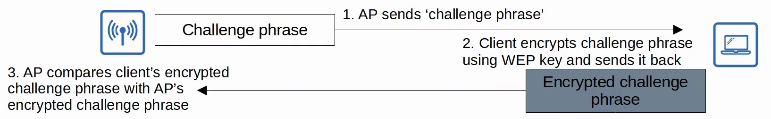
- EAP (Extensible Authentication Protocol)
- EAP is an authentication framework.
- It defines a standard set of authentication functions that are used by various EAP Methods.
- we will look at four EAP methods: LEAP, EAP-FAST, PEAP, and EAP-TLS.
- EAP is integrated with 802.1X, which provide port-based network access control.
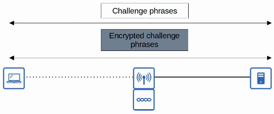
- LEAP (Lightweight EAP)
- LEAP was developed by Cisco as an improvement over WEP.
- Clients must provide a username and password to authenticate.
- In addition, mutual authentication is provided by both the client and server sending a challenge phrase to each other.
- Dynamic WEP keys are used, meaning that the WEP keys are changed frequently.
- Like WEP, LEAP is considered vulnerable and should not be used anymore.
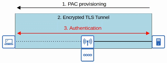
- EAP-FAST (EAP Flexible Authenticaiton via Secure Tunneling)
- EAP-FAST was also developed by Cisco.
- Consists of three phrases
- A PAC (Protected Access Credential) is generated and passed from the server to the client.
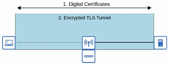
- A secure TLS tunnel is established between the client and authentication server.
- Inside of the secure (encrypted) TLS tunnel, the client and server communicate further to authenticate/authorize the client.
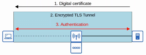
- PEAP (Protected EAP)
- Like EAP-FAST, PEAP involves establishing a secure TLS tunnel between the client and server.
- Instead of a PAC, the server has a digital certificate.
- The client uses this digital certificate to authenticate the server
- The certificate is also used to establish a TLS tunnel
- Because only the server provides a certificate for authentication, the client must still be authenticated within the secure tunnel, for example by using MS-CHAP (Microsoft Challenge-Handshake Authentication Protocol)
- EAP-TLS (EAP Transport Layer Security)
- Whereas PEAP only requires the AS to have a certificate, EAP-TLS requires a certificate on the AS and on every single client.
- EAP-TLS Is the most secure wireless authentication method, but it is more difficult to implement than PEAP because every client device needs a certificate.
- Because the client and server authenticate each other with digital certificates, there is no need to authenticate the client within the TLS tunnel.
- The TLS tunnel is still used to exchange encryption key information
Encryption and Integrity methods:
- TKIP (Temporal Key Integrity Protocol)
- Based on WEP, but more secure
- Should not be used in modern networks
- used in WPA
- CCMP (Counter/CBC-MAC Protocol)
- CCMP was developed after TKIP and is more secure.
- AES (Advanced Encryption Standard) counter mode for encryption
- AES is the most secure encryption protocol currently available. It is used widely used all over the world.
- There are multiple modes of operation for AES. CCMP uses ‘counter mode’.
- CBC-MAC for MIC to ensure integrity of messages
- used in WPA2
- GCMP (Galois/Counter Mode Protocol)
- GCMP is more secure and efficient that CCMP.
- increased efficiency allows higher data throughput than CCMP.
- GCMP consists of two algorithms:
- AES counter mode for encryption
- GMAC (Galois Message Authentication Code) for MIC to ensure the integrity of messages
- used in WPA3
1.12 Explain virtualization fundamenetals (server virtualization, containers, and VRFs)
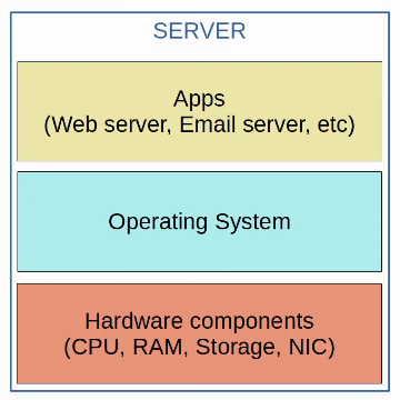
Before virtualization, there was a one-to-one relationship between a physical server and an operating system.
In that operating system, apps providing services such as a web server, email server, etc. would run.
One physical server would be used for the web server, one for the email server, one for the database server, etc.
This is inefficient for multiple reasons:
- Each physical server is expensive and takes up space, power, etc.
- The resources on each physical server (CPU, RAM, storage, NIC) are typically under-used.
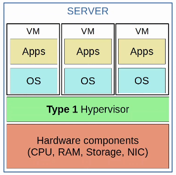
Type 1 Hypervisor
- Virtualization allows us to break the one-to-one relationship of hardware to OS, allowing multiple OS’s to run on a single physical server.
- Each instance is called a VM (Virtual Machine)
- A hypervisor is used to manage and allocate the hardware resources (CPU, RAM, etc) to each VM.
- Another name for a hypervisor is VMM (Virtual Machine Monitor)
- The type of hypervisor which runs directly on top of the hardware is called a Type 1 hypervisor.
- Examples include VMware ESXi, Microsoft Hyper-V, etc.
- Type 1 hypervisors are also called bare-metal hypervisors because they run directly on the hardware (metal).
- Another term is native hypervisor
- This is the type of hypervisor used in data center environments.
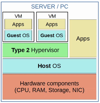
Type 2 Hypervisor
- Type 2 hypervisors run as a program on an operating system like a regular computer program.
- Examples include VMware Workstation, Oracle VirtualBox, etc.
- The OS running directly on the hardware is called the Host OS, and the OS running in a VM is called a Guest OS.
- Another name for a Type 2 hypervisor is hosted hypervisor.
- Although Type 2 hypervisors are rarely used in data center environments, they are common on personal-use devices (for example, if a Mac/Linux user needs to run an app that is only support on Windows, or vice versa)
Benefits of Virtualization:
- Partitioning
- Run multiple operating systems on one physical machine
- Divide system resources between virtual machines
- Isolation
- Provide fault and security isolation at the hardware level
- Preserve performance with advanced resource controls
- Encapsulation
- Save the entire state of a virtual machine to files
- Move and copy virtual machines as easily as moving and copying files
- Hardware Independence
- Provision or migrate any virtual machine to any physical server
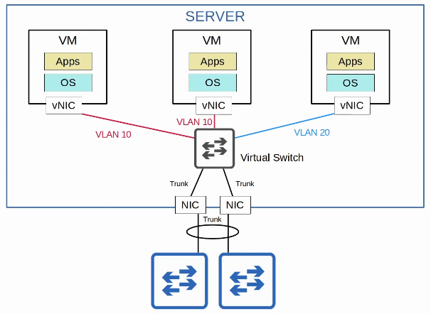
VMs are connected to each other and the external network via a virtual switch running on the hypervisor. Just like a regular physical switch, the vSwitch’s interfaces can operate as access or trunk ports and use VLANs to separate the VMs at Layer 2. Interfaces on the vSwitch connect to the physical NIC (or NICs) of the server to communicate with the external network.
1.13 Describe switching concepts
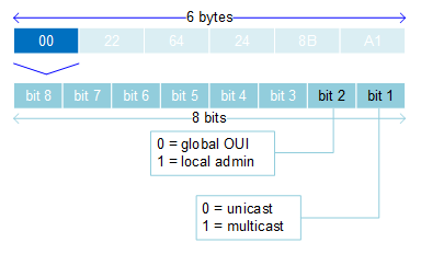
MAC Address is a 6-byte (48-bit) globally unique physical address assigned to the device when it is made. Written as 12 hexadecimal characters. (00:00:00:00:00:00)
OU:IO:UI:VE:ND:OR
- OUI - Organisationally Unique Identifier, ID assigned to a particular manufacturer
- VENDOR (NIC-specific identifier) - managed and assigned by the manufacturer, unique to each device
Unicast MAC addresses: actual MAC address showed above
Multicast MAC addresses: 01:00:5E-0F-0F-0F - 01-00-5E-7F-FF-FF
- 25th bit always 0, last 23 bits are created from last 23 bits of multicast IP address
Broadcast MAC addresses: FF:FF:FF:FF:FF:FF
Ethernet loopback testing MAC addresss: CF-00-00-00-00-00
MAC frame is generally comprised of nine fields, as shown in the following diagram:
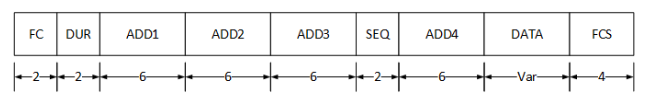
The Frame Control (FC) field is used to identify the type of 802.11 frame, and its 2 byes of data are subdivided into 11 related fields of information, such as wireless protocol, frame type, and frame subtype.
The duraction (DUR) field is a 2-byte field that is used mainly by control frames to indicate transmission timers. However, this field is also used by the Power Save (PS) Poll control frame to indicate the association identity (AID) of a client.
The address fields, ADD1, ADD2, ADD3 and ADD4, are 6-byte fields used to convey MAC address and BSSID information. What information resides in which address field is entirely dependent on the tpye of frame. However, ADD1, ADD2, ADD3 typically contain a source MAC address, destination MAC address, and BSSID with the order being dependent on whther the frame is entering the distribution system (DS), leaving the DS, Or passing directly between ad-hoc wireless devices. The ADD4 field is only present for frames passing between devices in the DS, such as from one access point (AP) to another AP, and is placed after the SEQ field.
The Sequence (SEQ) field is a 2-byte field that is subdivided to store two related pieces of information: the fragment number and sequence number of each frame.
The DATA portion of a frame varies in size and contains the frame’s payload. For data frames, the payload is user data. However, for other frames, such as management frames, this portion of the frame might contain information such as supported data rates and cipher suites.
Finally, the the Frame Check Sequence (FCS) field contains a 4-byte cyclic redundancy check (CRC) value calculated from all the 802.11 header fields, including the data portion of the frame. This value is used by the receiving station to determine whether the frame was corrupted during transit.
1.13.a MAC learning and aging
When a switch receives a frame, it associates the MAC address of source with the corresponding port which the frame was received. The switch dynamically constructs an address table using the MAC source addresses of received frames.
These dynamically learned MAC addresses are deleted from the table after the MAC address age value has expired. This frees unused addresses from the MAC address table for other active subscribers. The default value is 300 seconds.
Static MAC addresses can be assigned to the table, which are retained during a switch resest.
1.13.b Frame switching
The Content addressable Memory (CAM) table is used by a switch to discover the relationship between the OSI Layer 2 address of a device and the physical port used to reach the device. Switches make forwaarding decisions based on the destination MAC address contained in a frame’s header. The switch first searches the CAM table for an entry that matches the frame’s destination MAC address. If the frame’s destination MAC address is not found in the table, the switch forward the frame to all its ports, except the port from which it received the frame. If the destination MAC address is found in the table, the switch forrwards the frame to the appropriate port. The source MAC address is also recorded if it did not previous exist in the CAM table.
The Forwarding Information Base (FIB) is a table that contains all the prefixes from the IP routing table and is structured in a way that is optimized for forwarding. The FIB and the adjacency taable are the two main components of CEF, which is a hardware-based switching method that is implementeed in all OSI Layer 3-capable Catalyst switches. The FIB is synchronized with the IP routing table and therefore contains an entry for every IP prefix in the routing table. The IP prefixes are ordered so that when a Layer 3 address is compared against the FIB, the longest,most specific match will be found first; therefore, prefix lookup times are minimized.
The adjacency table maintains the Layer 2 addressing information for the FIB. Each network prefi in the FIB is associated with a next-hop address and an outbound interface. The adjacency table contains the Layer 2 addressing infromation for each next-hop address listed in the FIB amd is used to rewrite the Layer 2 header of each forwarded IP packet. You can issue the show adjacency command to display the contents of the adjacency table.
The Address Resolution Protocol (ARP) table conntains Layer 3 to Layer 2 address translations. Whenever the switch encounters a packet destined for a Layer 3 address that does not have an entry in the ARP table, the switch brodcast casts an ARP request to query the network for the Layer 2 address. When the ARP reply is received, the switch enters the address pair into the ARP table for future reference. You can issue the show ip arp comand to display the contents of the ARP table.
The VLAN table contains a record of the VLAN definitions on the switch and a list of the interfaces associates with each VLAN. The VLAN table does not contain any Layer 3 information. You can issue the show vlan command to display the contents of the VLAN table.
1.13.c Frame flooding
When the switch receives a frame for a destination MAC address that is not in its address table, it floods the frame out of all LAN ports of the same VLAN except for the port that the frame received.
When the destination station responds, the switch adds its relevant MAC source address and port ID to the address table.
1.13.d MAC address table
To exchange frames between LAN ports efficiently, the switch maintains a MAC address table. The switch learns and builds it’s address table through the processes described above, and is able to forward the subsequent frames to a single port without flooding all the LAN ports.
2.0 Network Access
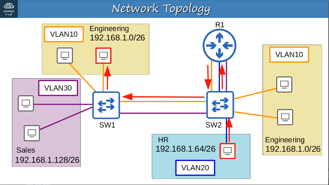
VLANs are configured on switches on a per-interface basis, and logically seperate end hosts at Layer 2. Switches do not forward traffic directly between hosts in different VLANs, it must forward the traffic to a router to perform inter-VLAN routing.
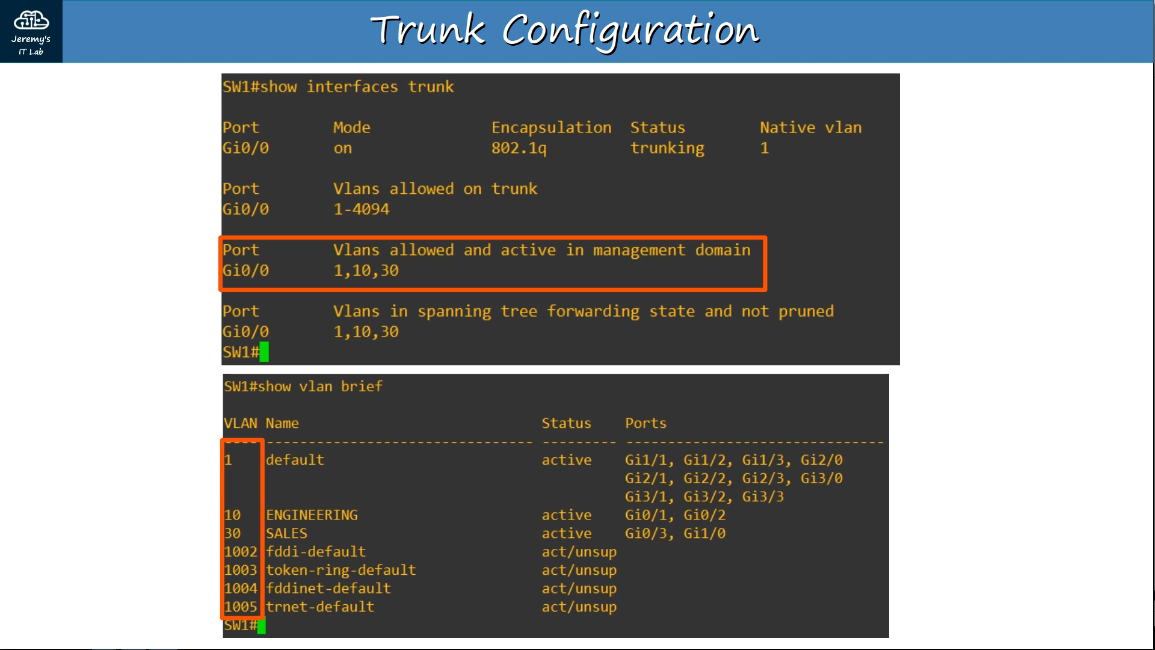
show vlan brief
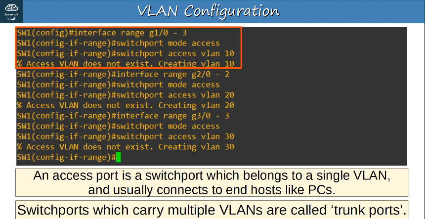
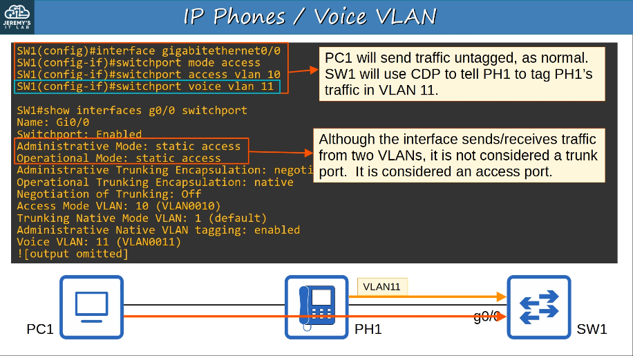
2.1.a Access ports (data and voice)
An access port is a switchport which belongs to a single VLAN, and usually connects to end hosts like PCs.
IP phones have an internal 3-port switch
- 1 port is the ‘uplink’ to the external switch
- 1 port is the ‘downlink’ to the PC
- 1 port connects internally to the phone itself
This allows the PC and the IP phone to share a single switch port. Traffic from the PC passes through the IP phone to the switch.
It is recommended to seperate ‘voice’ traffic (from the IP phone) and ‘data’ traffic (from the PC) by placing them in seperate VLANs.
- This can be accomplished using a voice VLAN
- Traffic from the PC will be untagged, but traffic from the phone will be tagged with a VLAN ID.
2.1.b Default VLAN
VLAN 1 is the default VLAN.
VLANs 1002-1005 exist by default and cannot be deleted. They are reserved for Token Ring and Fiber Distributed Data Interface (FDDI) VLANs. VLANs in this reserved range, as well as the switch’s native VLAN, can be modified but not deleted.
VLAN 0 is a special VLAN used by IP phones to indicate to an upstream switch that it is sending frames that have a configured 802.1p priority but that should reside in the native VLAN. This VLAN is used if voice traffic and data traffic should be seperated but do not require that a unique voice virtual VLAN be created.
VLAN 4094 is an extended VLAN and is not used for DTP frames unless it has been configured as the native VLAN.
VLAN IDs in the number range from 1006 through 4094 are available only on extended IOS images.
A VLAN ID can be a value from 1-1005 or 1-4094, depending on IOS images and switch model.
2.1.c Connectivity
Trunk ports = “tagged” ports
Access ports = “untagged” ports
DTP (Dynamic Trunking Protocol)
- Cisco proprietary protocol that allows Cisco switches to dynamically determine their interface status (access or trunk) without manual configuration. For security purposes, manual configuration is recommended and DTP should be disabled on all switchports.
- DTP uses the native VLAN to negotiate a trunk link when 802.1Q encapsulation is configured on the interface.
- Because DTP frames are always transmitted on the native VLAN, changing the native VLAN can have unexpected consequences. For example, if the native VLAN is not configured identically on both ends of a link, a trunk will not dynamically form.
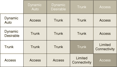
By default, all interfaces on a Cisco switch will use DTP to automatically negotiate whether an interface should be a trunk port or an access port.
There are two dynamic modes of operation for a switch port:
-
auto - operates in access mode unless the neighboring interface actively negotiates to operate as a trunk
-
desirable - operates in access mode unless it can actively negotiate a trunk connection with a neighboring interface.
VTP (VLAN Trunking Protocol)
- allows you to configure VLANs on a central VTP server switch, and other switches (VTP clients) will synchronize their VLAN database to the server. It is designed for large networks with many VLANs, but is rarely used and not recommended.
A switch can be configured for one of three VTP modes: server, client, or transparent. By default, Cisco switches are configured for VTP server mode.
VTP server mode allows you to create, modify, and delete VLANs in the VTP domain.However, a switch in VTP server mode will not originate VTP advertisements until a VTP domain name is set. VTP servers store VLAN configuration information in NVRAM, so if the switch is powered off, the VLAN configuration will be retained.
You cannot create, modify or delete VLANs on a switch that is operating in VTP client mode. However, a switch in VTP client mode can send its VLAN configuration information to other switches. In VTP v1 and VTP v2, VTP clients do not store the VLAN configuration information in NVRAM. In VTP v3, VTP clients do store VLAN configuration information in NVRAM.
A switch that is operating in VTP transparent mode does not participate in VTP. Any VLAN additions, changes, or deletions made to a switch in VTP transparent mode remain on the local switch and are not propagated to other switches.
However, a switch in VTP transparent mode can forward VTP advertisements received from other switches. Switches in VTP v2 transparent mode forward all VTP advertisements; switches in VTP v1 transparent mode will forward a VTP advertisement only if the VTP domain and VTP version number on the switch match that of the VTP advertisement. Like VTP servers, VTP transparent mode switches store VLAN configuration information in NVRAM.
2.2.a Trunk ports
In a small network with a few VLANs, itis possible to use a seperate interfaces for each VLAN when connected switches to switches, and switches to routers.
However, when the number of VLANs increases this is not viable. It will result in wasted interfaces, and often routers won’t have enough interfaces for each VLAN.
example:

Trunk ports can be used to carry traffic from multiple VLANs over a single interface. Switches will “tag” all frames that they send over a trunk link. This allows the reciving switch to know which VLAN the frame belongs to.
Trunk ports = ‘tagged’ ports
Access ports = ‘untagged’ ports
show interfaces trunk
show vlan brief


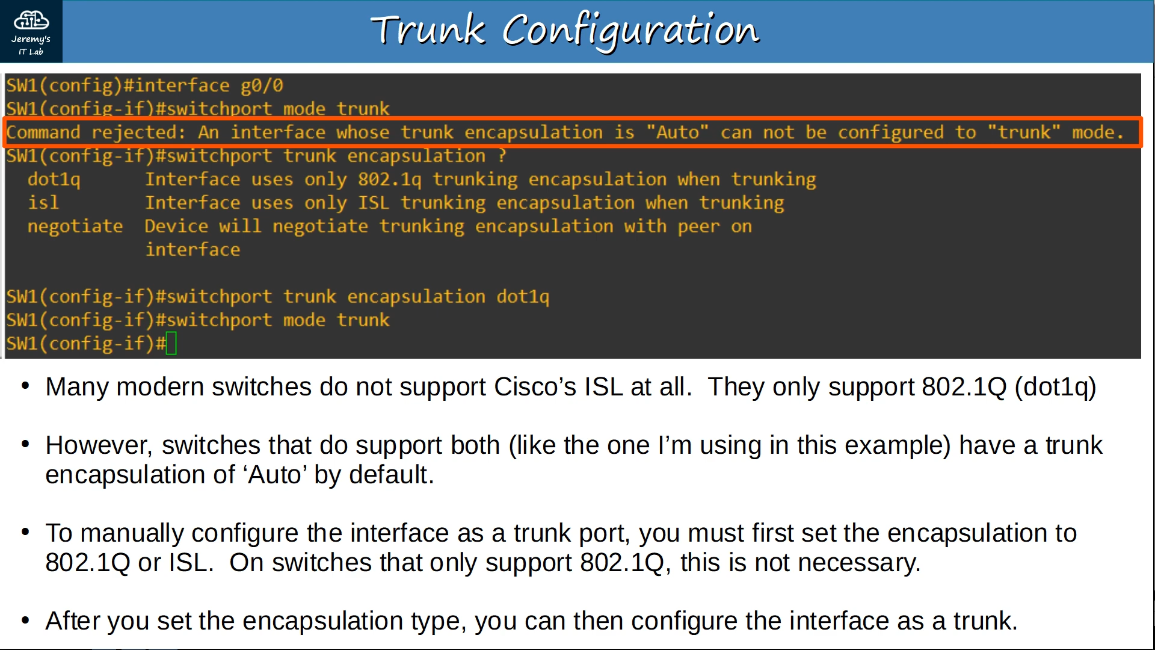
2.2.b 802.1q
802.1q is an industry standard trunking protocol.

The 802.1q tag is inserted between the Source and Type/Length fields of the Ethernet frame.
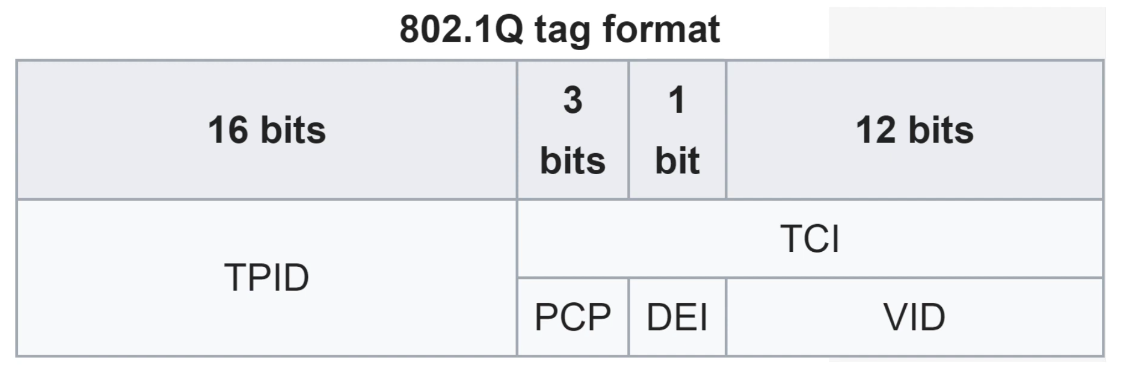
The tag is 4 bytes (32 bits) in length and consists of two main fields: TPID (Tag Protocol Identifier) and TCI (Tag Control Information).
The TPID is 2 bytes in length and is always set to a value of 0x8100, indicating the frame is 802.1q tagged.
The TCI consists of 3 smaller fields:
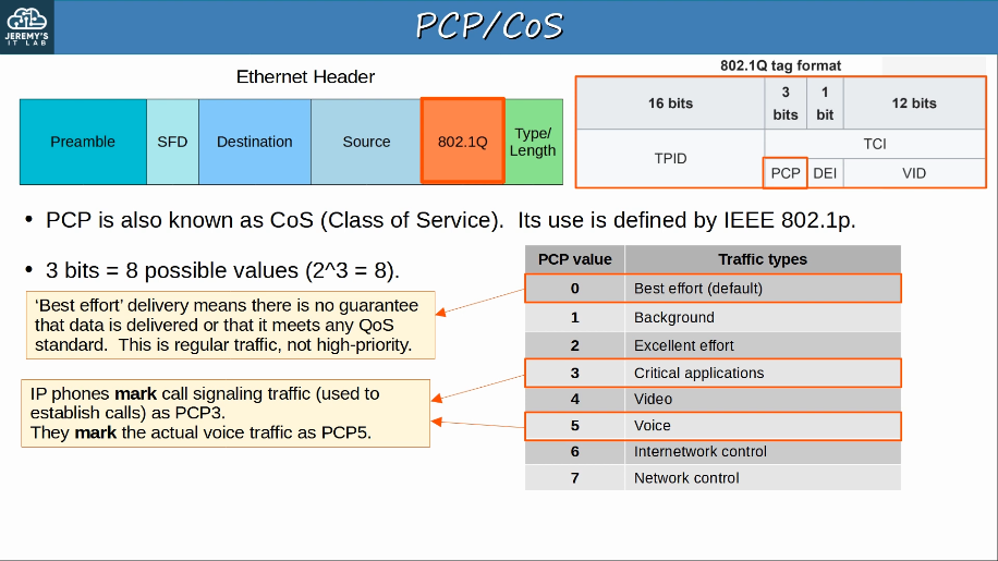
- PCP (Priority Code Point), 3 bits
- used for CoS (Class of Service), which prioritizes important traffic in congested networks
- DEI (Drop Eligiblle Indicator), 1 bit
- used to indicated frames that can be dropped if the network is congested.
- VID (VLAD ID), 12 bits
- identifies the VLAN the frame belongs to
- range of VLANs 1-4094
- Normal VLANs: 1-1005
- Extended VLANs: 1006-4094
2.2.c Native VLAN
802.1q has a feature called the native VLAN.
The native VLAN is VLAN 1 by default on all trunk ports, but can be manually configured on each trunk port.
The switch does not add an 802.1q tag to frames in the native VLAN.
When a switch receives an untagged frame on a trunk port, it assumed the frame belongs to the native VLAN. For this reason, it’s very important that the native VLAN matches for both switches.
R1(config-subif)#encapsulation dot1q (vlan-id) native
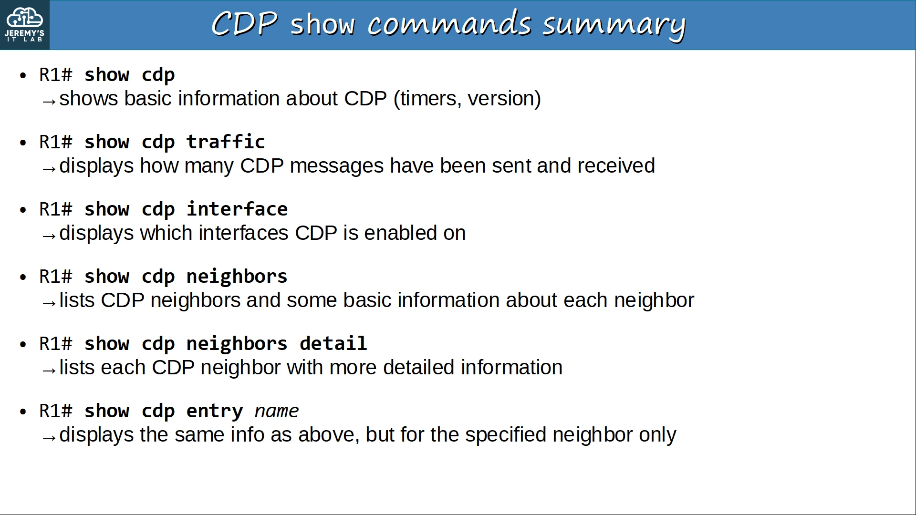
Layer 2 discovery protocols such as CDP and LLDP share information with and discover information about neighboring (connected) devices.
The shared information includes host name, IP address, device type, etc.
Because they share information about the devices in the network, they can be considered a security risk and are often not used. It is up to the network engineer/admin to decide if they want to use them in the network or not.
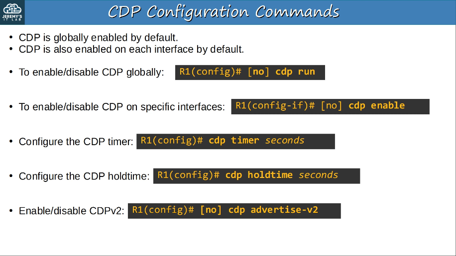
CDP (Cisco Discovery Protocol)
- It is enabled on Cisco devices (routers, switches, firewalls, IP phones, etc) by default.
- CDP messages are periodically sent to multicast MAC address 0100.0CCC.CCCC.
- When a device receives a CDP message, it processes and discards the message. It does NOT forward it to other devices.
- By default, CDP messages are sent once every 60 seconds. By default, the CDP holdtime is 180 seconds. If a message isn’t received from a neighbor for 180 seconds, the neighbor is removed from the CDP neighbor table.
- CDPv2 messages are sent by default.
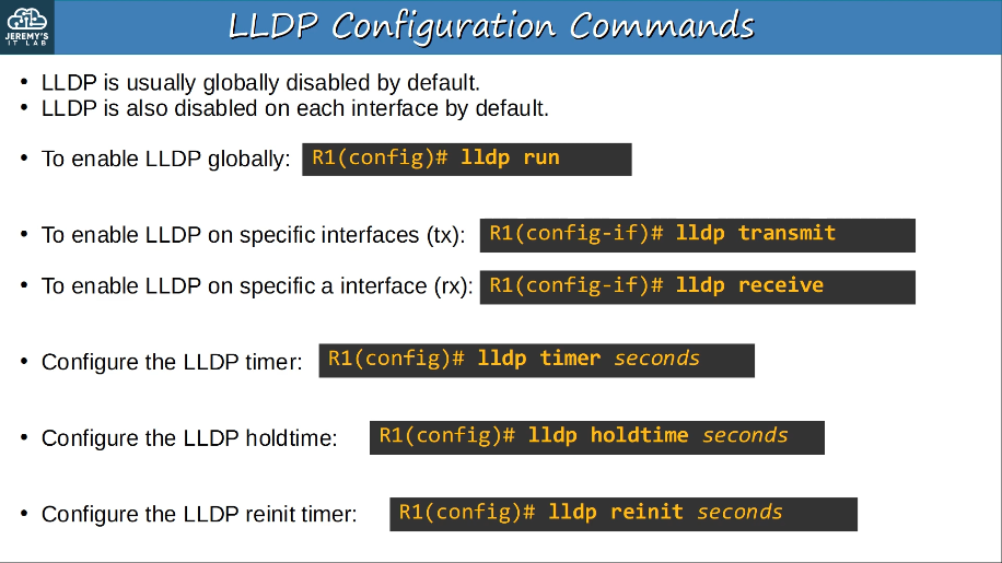
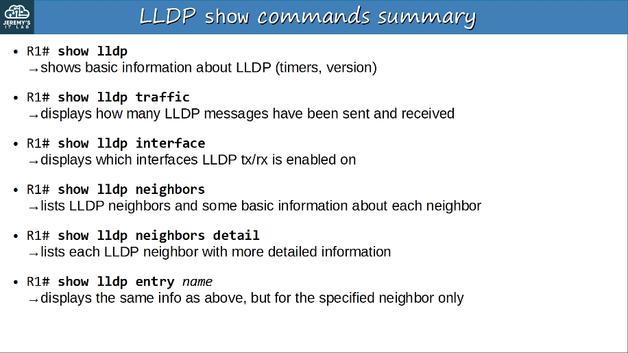
LLDP (Link Layer Discovery Protocol)
- LLDP is an industry standard protocol (IEEE 802.1AB)
- It is usually disabled on Cisco devices by default, so it must be manually enabled.
- A device can run CDP and LLDP at the same time.
- LLDP messages are periodically sent to multicast MAC address 0180.C200.000E.
- When a device receives an LLDP message, it processes and discards the message. It does NOT forward it to other devices.
- By default, LLDP messages are sent once every 30 seconds. By default, the LLDP holdtime is 120 seconds.
- LLDP has an additional timer called the “reinitialization delay”. If LLDP is enabled (globally or on an interface), this timer will delay the actual initialization of LLDP. 2 seconds by default.
When the bandwidth of the interfaces connected to end hosts is greater than the bandwidth of the connection to the distribution switch(es), this is called oversubscription, which can cause congestion.
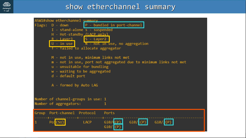
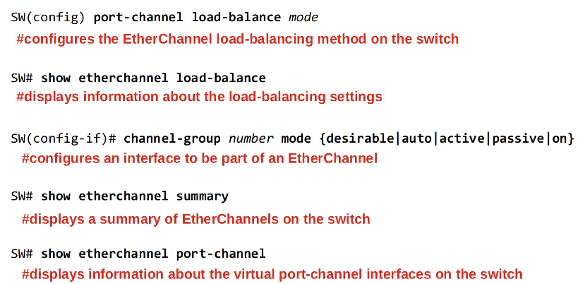
EtherChannel groups multiple interfaces together to act as a single interface. STP will treat this group as a single interface.
EtherChannel is also known as Port Channel, or LAG (Link Aggregation Group)
EtherChannel load balances based on “flows”. A flow is a communication between two nodes in the network. Frames in the same flow will be forwarded using the same physical interface.
The inputs used in the interface selection calculation can be configured
- inputs that can be used:
- Source MAC
- Destination MAC
- Source AND Destination MAC
- Source IP
- Destination IP
- Source and Destination IP
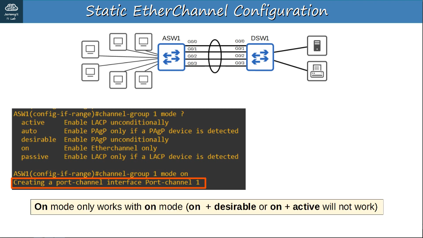
There are three methods of EtherChannel configuration on Cisco switches:
- LACP (Link Aggregation Control Protocol), 802.3ad
- Dynamically negoties the creation/maintenance of the the EtherChannel (similary to DTP for trunks)
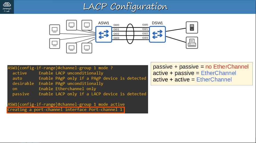
- PAgP (Port Aggregation Protocol)
- Cisco propretary protocol
- Dynamically negotiates the creation/maintenance of the EtherChannel.
- Static EtherChannel
- A protocol isn’t used to determine if an EtherChannel should be formed.
- Interfaces are statically configured to form an EtherChannel.
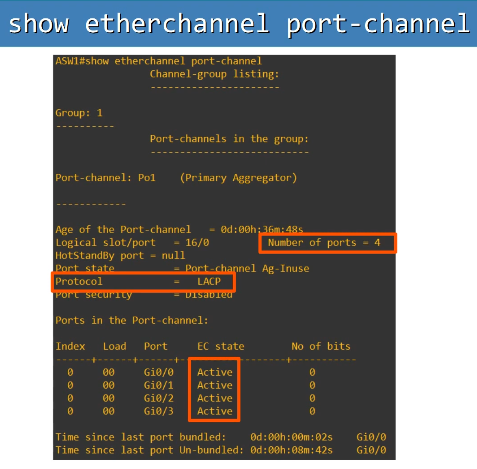
Up to 8 interfaces can be formed into a single EtherChannel (LACP allows up to 16, but only 8 will be active, the other 8 will be in standby mode, waiting for an active interface to fail.)
2.5 Interpret basic operations of Rapid PVST+ Spanning Tree Protocol
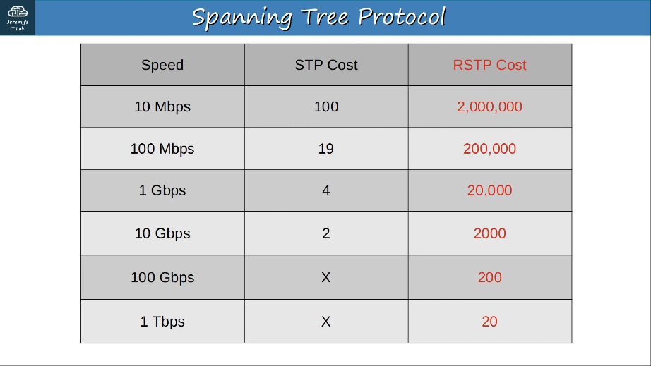
STP (Spanning Tree Protocol) prevents Layer 2 loops by placing redundant ports in a blocking state, essentially disabling the interface.
These interfaces act as backups that can enter a forwarding state if an active (=currently forwarding) interface fails.
Interfaces in a blocking state only send or receive STP messages (called BPDUs = Bridge Protocol Data Units)
Cisco switches use a version of STP called PVST+ (Per-VLAN Spanning Tree), which runs a seperate STP ‘instance’ in each VLAN, so in each VLAN different interfaces can be forwarding/blocking. This allows for load balancing by blocking different ports in each VLAN.
Rapid PVST+ allows for much faster converging/adapting to network changes, similar to 802.1w (Rapid Spanning Tree Protocol).
show spanning-tree
2.5.a Root port, root bridge (primary/secondary), and other port names
Switches use one field in the STP BPDU, the Bridge ID field, to elect a root bridge for the network.
The switch with the lowest Bridge ID becomes the root bridge. the default bridge priority is 32768 on all switches, so by default the MAC address is used as the tie-breaker (lowest MAC address becomes the root bridge). All ports on the root bridge are designated ports. Ports across from the root port are always designated ports.
Each remaining switch will select ONE of its interfaces to be its root port.
Root port selection:
- Lowest root constructors
- Lowest neighbor bridge ID
- Lowest neighbor port ID
Each remaining Collisions Domain will select ONE interface to be a designated port (forwarding state). The other port in the collision domain will be non-desingated (blocking).
- Designated port selection:
- Interface on switch with the lowest root cost
- Interface on switch with the lowest bridge ID
In RSTP, the non-designated port is split into two seperate roles:
- the alternate port role (blocking)
- the backup port role (two interfaces on same collision domain, via a hub)
spanning-tree vlan 10 root primary/secondary
- root primary = STP priority 24576
- root secondary = STP priority 28672
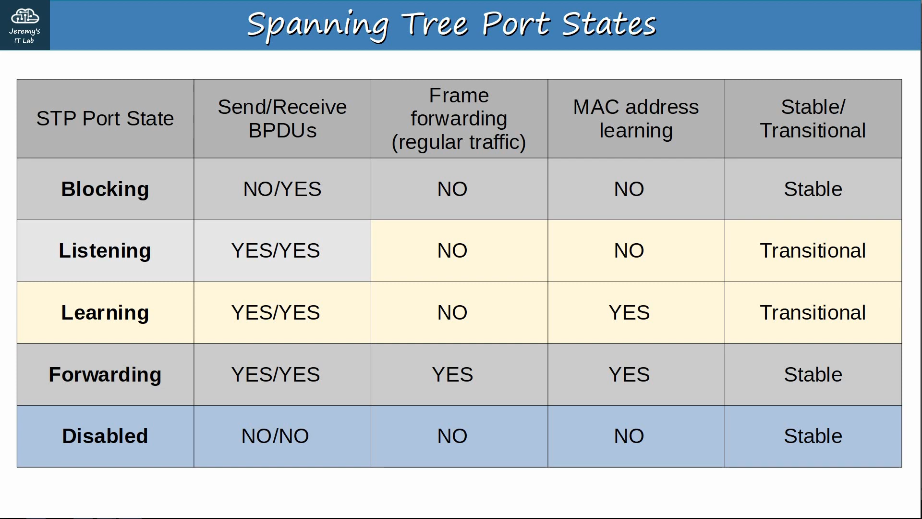
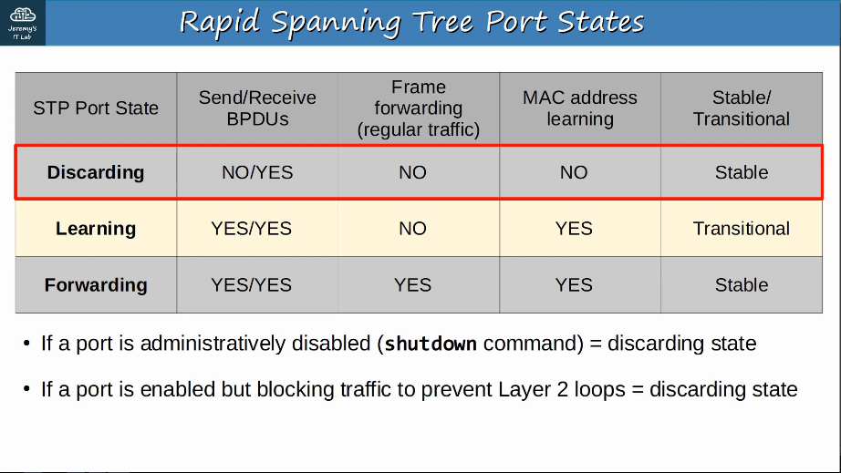
2.5.b Port states (forwarding/blocking)
Root/Designated ports remain stable in a Forwarding state.
Non-designated ports remain stable in a Blocking state. Interfaces in a Blocking state are effectively disabled to prevent loops.
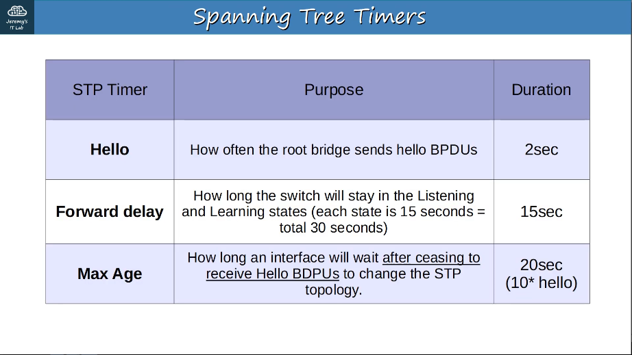
Listening and Learning are transitional states which are passed through when an interface is activated, or when a Blocking port must transition to a Forwarding state due to a change in the network topology.
2.5.c PortFast
Portfast allows a port to move immediately to the Forwarding state, bypassing Listening and Learning. If used, it must be enabled only on ports connected to end hosts. If enabled on a port connected to another switch it could cause a Layer 2 loop.
BPDU guard is another optional STP feature
- can be used to prevent an access port from participating in the spanning tree.
SW1(config-if)#spanning-tree portfast (default)
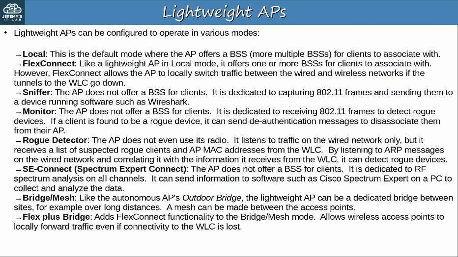
2.6 Describe Cisco Wireless Architectures and AP modes
APs can operate in additonal modes beyond the ones we’ve introduced so far (section 1.11.b)
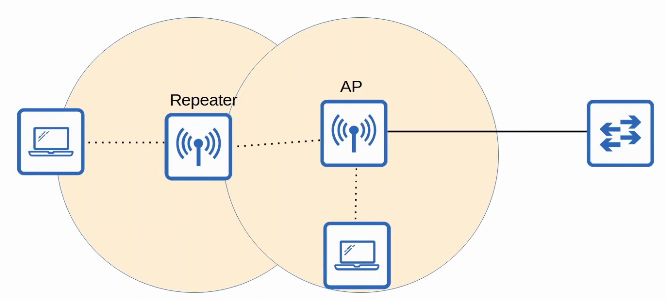
An AP in repeater mode can be used to extend the range of a BSS.
- The repeater will simply retransmit any signal it receives from the AP.
- A repeater with a single radio must operate on the same channel as the AP, but this can drastically reduce the overall throughput on the channel.
- A repeater with two radios can receive on one channel, and then retransmit on another channel.
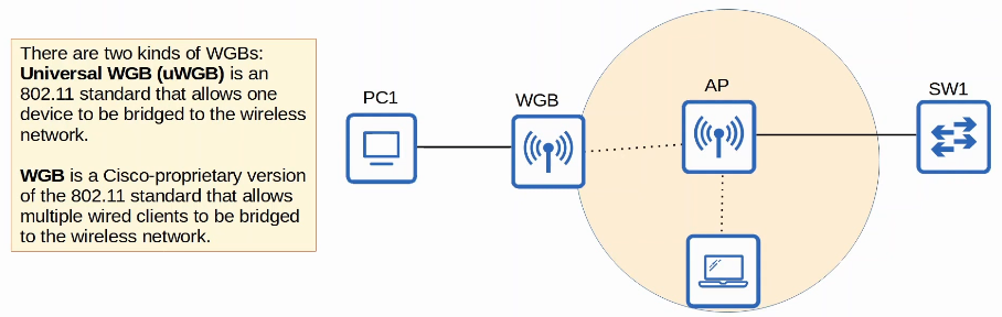
An AP in Workgroup Bridge (WGB) mode operates as a wireless client of another AP, and can be used to connect wired devices to the wireless network.
- In the example below, PC1 does not have wireless capabilities, and also does not have access to a wired connection to SW1.
- PC1 has a wired connection to the WGB, which has a wireless conection to the AP.
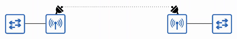
An AP in outdoor bridge mode can be used to connect network over long distances without a physical cable connecting them.
- The APs will use specialized antennas that focus most of the signal power in one direction, which allows the wireless connection to be made over longer distances than normally possible.
- The connection can be point-to-point as in the diagram below, or point-to-multipoint in which multiple sites connect to one central site.
review of wireless topics:
There are three main wireless AP deployment methods:
- Autonomous
- Lightweight
- Cloud-based
Autonomous APs are self-contained systems that don’t rely on a WLC.
- Autonomous APs connect to the wired network with a trunk link.
- Data traffic from wireless clients has a very direct path to the wired network or to other wireless clients associated with the same AP.
- Each VLAN has to stretch across the entire network. This is considered bad practice.
- Large broadcast domains
- Spanning tree will disable links
- Adding/deleting VLANs is very labor-intensive
- Autonomous AP’s can be used in small networks, but they are not viable in medium to large networks.
- Large networks can have thousand of APs.
- Autonomous APs can also function in the modes covered previously: Repeater, Outdoor Bridge, Workgroup Bridge
The functions of an AP can be split between the AP and a Wireless LAN Controller (WLC).
Lightweight APs handle ‘real-time’ operations like transmitting/receiving RF traffic, prioritizing packets, encryption/decryption of traffic, sending out beacons/probes, etc
- Other functions are carried out by a WLC, for example RF management, security/QoS management, client load balancing, client authentication, client association/roaming management, etc.
- This is called split-MAC architecture.
- The WLC is also used to centrally configure the lightweight APs.
- The WLC can be located in the same subnet/VLAN as the lightweight APs it manages, or in a different subnet/VLAN.
- The WLC and the lightweight APs authenticate each other using digital certificates installed on each device (X.509 standard certificates)
- This ensures that only authorized APs can join the network.
The WLC and lightweight APs use a protocol called CAPWAP (Control and Provisioning Of Wireless Access Points) to communicate.
- Based on an older protocol called LWAPP (Lightweight Access Point Protocol)
Two tunnels are created between each AP and the WLC:
- Control tunnel (UDP port 5246). This tunnel is used to configure the APS, and control/manage the operations. All traffic in this tunnel is encrypted by default.
- Data tunnel (UDP port 5247). All traffic from wireless clients is sent through this tunnel to the WLC. It does not go directly to the wired network.
- Traffic in this tunnel is not encrypted by default, but you can configure it to be encrypted with DTLS (Datagram Transport Layer Security)
- Because all traffic from wireless clients is tunneled to the WLC with CAPWAP, AP’s connect to switch access ports, not trunk ports.
There are some key benefits to split-MAC architecture, here are a few:
- Scalability: With a WLC (or multiple in very large networks) it’s much simpler to build and support a network with thousands of APs.
- Dynamic channel assignment: The WLC can automatically select which channel each AP should use.
- Transmit power optimization: The WLC can automatically set the appropriate transmit power for each AP.
- Self-healing wireless coverage: When an AP stops functioning, the WLC can increase the transmit power of nearby APs to avoid coverage holes.
- Seamless roaming: Clients can roam between APS with no noticeable delay.
- Client load balancing: If a client is in range of two APs, the WLC can associate the client with the least-used AP, to balance the load among APs.
- Security/QoS management: Central management of security and QoS policies ensures consistency across the network.
FlexConnect ACLs are supported on the native VLAN. FlexConnect ACLs are simiilar to traditional Cisco ACLs in that they are rules that permit or deny traffic from a given source to a given destination. However, FlexConnect ACLs are configured on Cisco wireless lightweight AP VLAN interfaces if the lightweight AP is operating in FlexConnect mode.
FlexConnect ACLs are applied per AP and per VLAN. One possible application of FlexConnect ACLs is to prevent administration of the WLAN from a particular VLAN. Even though FlexConnect ACLs are applied differently than traditional ACLs, it is important to name FlexConnect ACLs differently from any traditional ACLs that might be configured on the WLAN.
FlexConnect ACLs cannot be configured with a per-rule direcion. This is in contrast to a traditional ACL, which can be configured with inbound rules or outbound rules. A FlexConnect ACL is applied in the ingress direction or the egress direction as an entire set of rules, not on a per-rule basis.
FlexConnect ACLs support the implicit deny rule. In this way, FlexConnect ACLs work similarly to traditional ACLs.
Cloud-Based AP architecture is in between autonomous AP and split-MAC architecture.
- Autonomous APs that are centrally managed in the cloud.
- Cisco Meraki is a popular cloud-based Wi-Fi solution.
- The Meraki dashboard can be used to configure APs, monitor the network, generate performance reports, etc.
- Meraki also tells each AP which channel to use, what transmit power, etc.
- However, data traffic is not sent to the cloud. It is sent directly to the wired network like when using autonomous APs.
- Only management/control traffic is sent to the cloud.
2.7 Describe physical infrastructure connections of WLAN components (AP, WLC, access/trunk ports, and LAG)
- WLC ports are the physical ports that cables connect to.
- WLC interfaces are the logical interfaces within the WLC (ie. SVIs on a switch).
- WLCs have a few different kinds of ports:
- Service port: A dedicated management port. Used for out-of-band management. Must connect to a switch access port because it only supports one VLAN. This port can be used to connect to the device while it is botting, perform system recovery, etc.
- Distribution system port: These are the standard network ports that connect to the ‘distribution system’ (wired network)
- Console port: This is a standard console port, either RJ45 or USB.
- Redundancy port: This port is used to connect to another WLC to form a high availability (HA) pair.
WLCs have a few different kinds of interfaces:
- Management interface: Used for management traffic such as Telnet, SSH, HTTP, HTTPS, RADIUS authentication, NTP, Syslog, etc. CAPWAP tunnels are also formed to/from the WLC’s management interface.
- Redundancy management interface: When two WLCs are connected by their redundancy ports, one WLC is ‘active’ and the other is ‘standby’. This interface can be used to connect to and manage the ‘standby’ WLC.
- Virtual interface: This interface is used when communicating with wireless clients to relay DHCP requests, perform client web authentication, etc.
- Sevice port interface: If the service port is used, this interface is bound to it and used for out-of-band management.
- Dynamic interface: These are the interfaces used to map a WLAN to a VLAN. For example, traffic from the ‘Internal’ WLAN will be sent to the wired network from the WLC’s ‘Internal’ dynamic interface.
LAG (Link Aggregation)
- Similar to EtherChannel on switches, LAG enables multiple physical ports on a WLC to operate as one logical group. Thus, LAG enables load balancing across links between devices and redundancy. If one link fails, the other links in the LAG bundle will continue to function.
- By default all eight ports will be included in the LAG bundle if you have enabled LAG on a Cisco WLC that contains eight distribution system ports.
- A distribution system port is a data port that typically conenects to a switch in 802.1Q trunk mode.
- LAG requires only one functional physical port in order to pass client traffic
- If all but one port in a LAG bundle fails, that port will pass client traffic for all failed ports.
- Distribution system ports can be configured to work in pairs or independently of each other if LAG is disabled. By default, a Cisco WLC’s distribution system port operate in 802.1Q trunk mode, forming a trunk link between each WLC distribution system port and the switch to which it is connected.
- When enabled, LAG modifies this config so that the ports are bundled and no longer operate as independent trunk links.
2.8 Describe AP and WLC management access connections (Telnet, SSH, HTTP, HTTPS, console, and TACACS+/RADIUS)
WLC config:
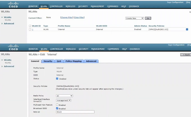
In split-MAC architecture, there are four man WLC deployment models:
-
Unified AP deployment: The WLC is a hardware appliance in a central location of the network.
-
Cloud-based AP deployment: The WLC is a VM running on a server, usually in a private cloud in a data center. This is not the same as the cloud-based AP architecture discussed previously.
-
Embedded AP deployment: The WLC is integrated within a switch.
-
Mobility Express AP deployment: The WLC is integrated within an AP.
CPU ACLs are used to limit access to the CPU of the WLC. This limits which devices will be able to connect to the WLC via Telnet/SSH, HTTP/HTTPS, retrieve SNMP information from the WLC, etc.
2.9 Interpret the wireless LAN GUI configuration for client connectivity, such as WLAN creation, security settings, QoS profiles, and advanced settings
Day 58 video
To create a new normal WLAN, you should complete four steps on the WLANS > New page of the WLC GUI:
- Select the type of WLAN you are creating from the Type drop-down list box; by default, this value is configured to (normal) WLAN.
- There are 3 types of WLANs you can create by using the WLC GUI:
- A normal WLAN, which is the WLAN to which wireless clients inside your company’s walls will connect
- A Guest LAN, which is the WLAN to which guest wireless clients inside your company’s walls will connect
- A Remote LAN, which is the WLAN configuration for wired ports on the WLC
- Enter a 32-character or less profile name in the Profile Name field.
- the profile name should uniqely identify the WLAN that you are configuring. The value you enter in the profile name field will be used by the WLC to identify the WLAN on other configuration pages.
- for simplicity, many adminstrators choose to use the same value for the profile name field as they plan to configure in the SSID field.
- Enter a 32-character or less SSID in the SSID field.
- SSID is the WLAN network name that will be broadcast to wireless clients.
- Choose a WLAN ID from the ID drop-down list box.
- By default the ID will be configured to a value of 1. can be configured in the range from 1-512. Although Cisco controllers support a maximum of 512 WLANs, only 16 can be actively configured.
QoS:
- Platinum (voice)
- Gold (video)
- Silver (best effort)
- Bronze (background)
3.0 IP Connectivity
Routers can use dynamic routing protocols to advertise information about the routes they know to other routers.
They form ‘adjacencies’ / ‘neighbor relationships’ / ‘neighborships’ with adjacent routers to exchange this information.
If multiple routes to a destination are learned, the router determines which route is superior and adds it to the routing table. It uses the ‘metric’ of the route to decide which is superior (lower metric = superior).
Dynamic routing protocols can be divided into two main categories:
IGP (Interior Gateway Protocol)
- used to share routes wihin a single autonomous system (AS), which is a single organization (ie. a company)
- ex. RIP (Routing Information Protocol), EIGRP (Enhanced Interior Gateway Routing Protocol) using a Distance Vector algo
- ex. OSPF (Open Shortest Path First) and IS-IS (Intermediate System to Intermediate System) (IS-IS) using a Link State algo
EGP (Exterior Gateway Protocol)
- used to share routes between different autonomous systems
- ex. BGP (Border Gateway Protocol) using a Path Vector algo
3.1 Interpret the components of routing table
3.1.a Routing protocol code
3.1.b Prefix
3.1.c Network mask
3.1.d Next Hop
3.1.e Administrative distance
In most cases a company will only use a single IGP, usually OSPF or EIGRP.
However, in some rare cases they might use two. For example, if two companies connect their networks to share information, two different routing protocols might be in use.
Metric is used to compare routes learned via the same routing protocol. Different routing protocls use different metrics, so they cannot be compared. Instead, the AD (Administrative Distance) is used to determine which routing protocol is preferred.
A lower AD is preferred, and indicates that the routing protocol is considered more trustworthy (more likely to select good routes).
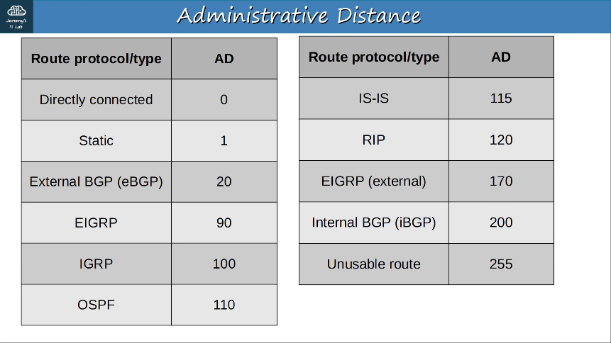
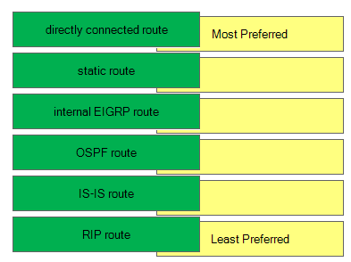
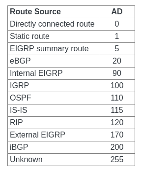
3.1.f Metric
A router’s route table contains the best route to each destination network it knows about.
If a router using a dynamic routing protocol learns two different routes to the same destination, how does it determine which is ‘best’?
It uses the metric value of the routes to dtermine which is best. A lower metric = better.
Each routing protocol uses a different metric to determine which route is best.
If a router learns two (or more) routes via the same routing protocol to the same destination (same network address, same subnet mask) with the same metric, both will be added to the routing table. Traffic will be load-balanced over both routes.
ECMP (Equal Cost Multi-Path) is a routing strategy where packets towards a single destination IP address are load-balanced over multiple best paths with equal metrics.
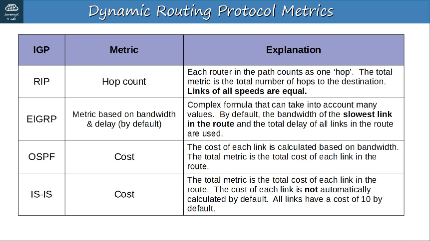
EIGRP uses bandwidth and delay to calculate metric by default. Bandwidth refers to the data throughput of a link. Delay refers to the length of time required to send a packet to a destination.
EIGRP can also use load and reliability as components, but these components are not used by default. Load refers to the amount of data activity over a link. Reliability refers to the bit-error rate of a link.
OSPF and IS-IS use cost to calculate the best path to a destination network. By default, OSPF and IS-IS calculate the cost based on bandwidth. However, cost can be configured by using any value that an adminstrator desires, such as the monetary cost of using a link.
RIPv1 and RIPv2 use hop count to calculate the best path to a destination network. Hop count refers to the number of routers a packet will traverse from source to destination. However, RIP has a hop-count limitation of 15 hops; any route more than 15 hops away is considered to be unreachable. With a defined maximum metric, a routing protocol can mitigate routing loops caused by invalid routing updates.
3.1.g Gateway of last resort
3.2 Determine how a router makes a forwarding decision by default
How does a Cisco Layer 3 device, such as a router, decides which route to use?
-
Prefix length – the longest prefix match is always preferred. For example, a /24 route wins over a /16 route.
-
Administrative Distance (AD) – if the routes have the same prefix lengths and are using different routing protocols, then the route with the lowest Administrative Distance wins. For example, OSPF routes are more preferred than RIP routes by default.
-
Metric – if the routes have the same prefix length and administrative distance, then it will come down to the metrics. So the router learns about multiple different paths going to the same destination, using the same routing protocol, a measure called metric is used to decide. The path with lower metric wins.
Routers drop packets with unknown destinations.
3.2.a Longest prefix match
When a router looks up a destination address in its routing table, it looks for the most specific matching route. Most specific = longest prefix length ( /32 > /24 > /16 > /8 > /0)
3.2.b Administrative distance
3.2.c Routing protocol metric
IPv6 routing works the same as IPv4 routing.
However, the two processes are seperate on the router, and the two routing tables are seperate as well.
IPv4 routing is enabled by default. IPv6 routing is disabled by default, and must be enabled with “ipv6 unicast-routing”
If IPv6 routing is disabled, the router will be able to send and receive IPv6 traffic, but will not route IPv6 traffic (=will not forward it between networks).
A connected network route is automatically added for each connected network.
A local host route is automatically added for each address configured on the router.
Routes for link-local addresses are not added to the routing table.
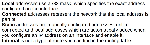
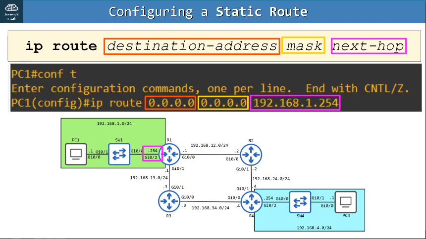
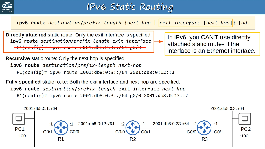
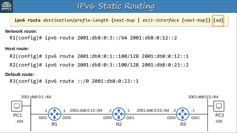
to configure:
ip route (destination network ip address) (mask) (next-hop ip address)
ip route (destination network ip address) (mask) (exit-interface)
to verify:
show ip route
3.3.a Default route
A route that a router uses to forward an incoming packet when no other route is available for that packet in the routing table.
3.3.b Network route
A route to a network/subnet (mask length < /32)
3.3.c Host route
Local host routes are marked with an **L in the output of the show ip route command or the show ipv6 route commmand.
IPv4 host routes have a /32 mask, and IP version 6 (IPv6) host routes have a /128 mask.
Not all IPv4 routes with a /32 mask are considered host routes. IPv4 addresses that are manually configured with a /32 mask are considered to be connected addresses and are marked wtih a C in the output of the show ip route command.
-example picture—
3.3.d Floating static
By changing the AD of a static route, you can make it less preferred than routes learned by a dynamic routing protocol to the same destination (make sure the AD is higher than the routing protocol’s AD!) This is known as a “floating static route”.
Floating static routes are used to provide link redundancy.
The route will be inactive (not in the routing table) unless the route learned by the dynamic routing protocol is removed or no longer available.
OSPF (Open Shortest Path First) is a link routing protocol.
OSPF uses shortest path first algorithm, aka Dijkstra’s algorithm.
Routers store information about the network in LSAs (Link State Advertisements), which are organized in a structure called the LSDB (Link State Database)
Routers will flood LSAs until all routers in the OSPF area develop the same map of the network (LSDB).
OSPF areas
- An area is a set of routers and links that share the same LSDB
- The backbone area (area 0) is an area that all other areas must connect to.
- Routers with all interfaces in the same area called internal routers.
- Routers with interfaces in multiple areas are called area border routers (ABRs).
- Routers connected to the backbone area (area 0) are called backbone routers.
- An intra-area route is a route to a destination inside the same OSPF area.
- An interarea route is a route to a destination in a different OSPF area.
- OSPF areas should be contiguous.
- All OSPF areas must have at least one ABR connected to the backbone area.
- OSPF interfaces in the same subnet must be in the same area.
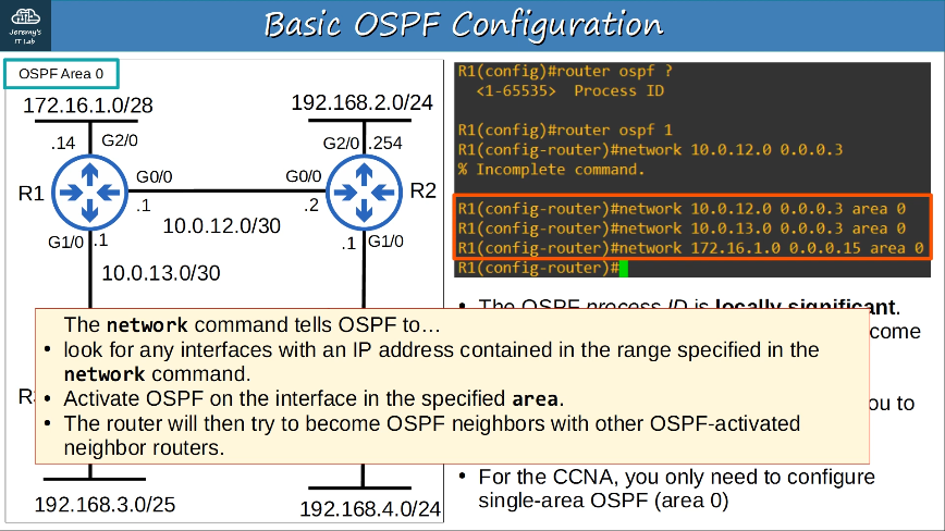
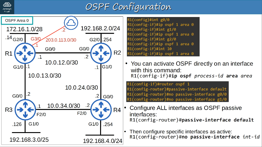
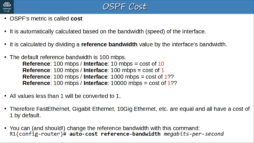
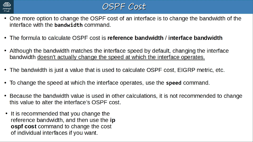
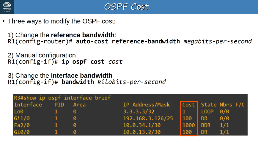
3.4.a Neighbor adjacencies
In OSPF, there are three main steps in the process of sharing LSAs and determining the best route to each destination in the network.
- Become neighbors with other routers connected to the same segment
- Exchange LSAs with neighbor routers
- Calculate the best routes to each destination, and insert them into the routing table
When an OSPF neighbor router is powered on, it transitions through the following neighbor states:
- Down
- Init
- 2-Way
- Exstart
- Exchange
- Loading
- Full
An OSPF neighbor router begins in the Down state. A neighbor in the Down state has not yet sent a Hello packet.
When a hello packet is received from the neighbor router but the Hello packet does not contain the receiving router’s ID, the neighbor router is in the Init state. The receiving router replies to the neighbor router with a Hello packet that contains the neighbor router’s ID as an acknowledgment that the receiving router received the neighbor’s Hello packet. If a arouter is stuck in the Init state, it has sent Hello packets but has no received any from the neighbor router.
The neighbor router replies with a Hello packet that contains the receiving router’s ID. When this occurs, the neighbor router is in the 2-Way state. At the end of the 2-Way state, the DR and BDR are elected for broadcast and nonbroadcast multiaccess (NBMA) networks.
On broadcast and NBMA networks, neighbor routers will proceed to the Full state with only the DR and BDR; other neighbor adjancies will remain in the 2-Way state. If all routers on a segment remain in the 2-Way state, you should verify whether all routers on the segment are set to a priority of 0, which prevents any of them from becoming the DR or BDR.
After the DR and BDR are elected, neighbor routers form master-slave relationships in order to establish the method for exchanging link-state information. Routers in this state are in the Exstart state. If a router is stuck in the Exstart state, you should verify whether there is a problem with mismatched maximum transmission unit (MTU) settings between two routers or duplicate router IDs.
Neighbor routers then exchange database descriptor (DBD) packets. These DBD packets contain link-state advertisement (LSA) headers that describe the contents of the link-state database (LSDB). Routers in this state are in the Exchange state. If a router is stuck in the Exchange state, you should verify whether there is a problem with mismatched MTU settings or duplicate router IDs.
Routers then send link-state request (LSR) packets to request the contents of the neighbor router’s OSPF database. The neighbor router replies with link-state update (LSU) packets that contain the routing database information. Routers in this state are in the Loading state. If a router is stuck in the Loading state, you should verify whether there is a problem with mismatched MTU settings or corrupted LSR packets.
After the OSPF databases of neighbor routers are fully synchronized, the routers transition to the Full state, which is the normal OSPF router state for DRs and BDRs. A router will periodically send Hello packets to its neighbors to indicate that it is still functional. If a router does not receive a Hello packet from a neighbor within the dead timer interal, the neighbor router will transition back to the Down state.
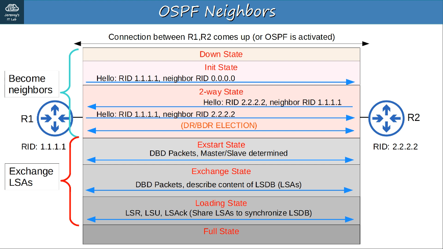
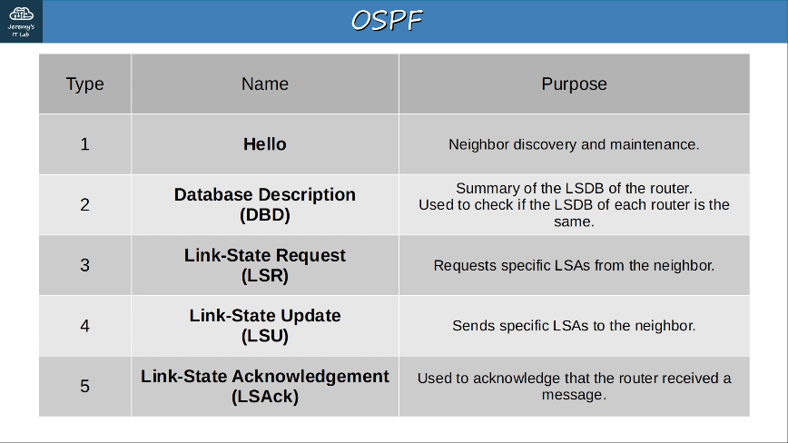
OSPF Neighbor requirements
- Area number must match
- Interfaces must be in the same subnet
- OSPF process must not be shutdown
- OSPF Router IDs must be unique
- Hello and Dead timers must match
- Authentication settings must match
- IP MTU settings must match (can become neighbors, but OSPF doesn’t operate properly)
- OSPF network type must match (can become neighbors, but OSPF doesn’t operate properly)
3.4.b Point-to-point
Point-to-point network type is enabled on serial interfaces using the PPP or HDLC encapsulations by default.
Routers dynamically discover neighbors by sending/listening for OSPF Hello messages using multicast address 224.0.0.5.
A DR and BDR are not elected. The two routers will form a Full adjacency with eachother.
3.4.c Broadcast (DR/BDR selection)
Broadcast network type is enabled on Ethernet and FDDI interfaces by default.
Routers dynamically discover neighbors by sending/listening for OSPF Hello messages using multicast address 224.0.0.5. To send routing information to a DR or BDR the multicast address of 224.0.0.6 is used.
A DR (designated router) and BDR (backup designated router) must be elected on each subnet (only DR if there are no OSPF neighbors).
Routers which aren’t the DR or BDR become a DROther.
The DR/BDR election order of Priority:
- Highest OSPF interface priority (same by default)
- Highest OSPF Router ID
- highest IP address on a loopback interface
- highest IP address on a non-loopback interface
“First place” becomes the DR for the subnet, “second place” becomes the BDR
The default OSPF interface priority is 1 on all interfaces.
In the broadcast network type, routers will only form a full OSPF adjacency with the DR and BDR of the segment. Therefore, routers only exchange LSAs with the DR and BDR. DROthers will not exchange LSAs with each other. All routers will still have the same LSDB, but this reduces the amount of LSAs flooding the network.
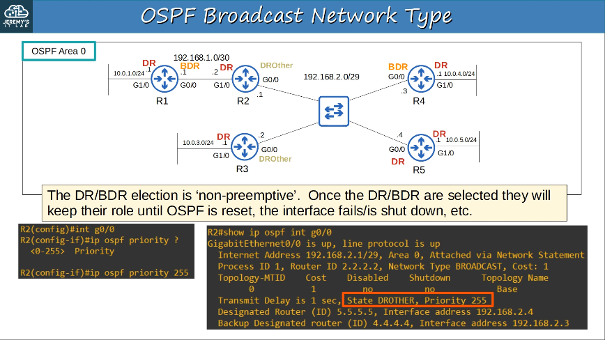
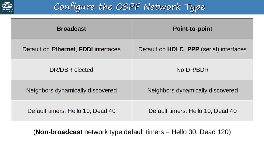
3.4.d Router ID
OSPF uses the largest IP address configured on the interfaces as its router ID. If a loopback interface is configured with an IP address, the Cisco IOS software will use this IP address as its router ID.
3.5 Describe the purpose, functions, and concepts of first hop redundancy protocols
A (FHRP) First Hop Redundancy Protocol is a computer networking protocol which is designed to protect the default gateway used on a subnetwork by allowing two or more routers to provide backup for the gateway address; in the event of failure of an active router, the backup router will take over the address, usually within a few seconds.
A virtual IP is configured on the two routers, and a virtual MAC is generated for the virtual IP (each FHRP uses a different format for the virtual MAC)
An active router and a standby router are elected. (different FHRPs use different terms)
End hosts in the network are configured to use the virtual IP as their default gateway.
The active router replies to ARP requests using the virtual MAC address, so traffic destined for other networks will be sent to it.
If the active router fails, the standby becomes the next active router. The new active router will send gratuitous ARP messages so that switches will update their MAC address tables. It now functions as the default gateway.
If the old active router comes back online, by default it won’t take back its role as the active router. It will become the standby router (“non-preemptive”)
Preemption can be configured, so the old router does take back its old role.
List of FHRPs:
- HSRP (Hot Standby Router Protocol)
- HSRP is a Cisco-properitary protocol that enables multiple routers to function as a single gateway for the network.
- HSRP configures two or more routers to share a virtual Internet Protocol (IP) address and a virtual MAC address so that the group of routers appears as a single device to other hosts on the network.
- Based on priority value, HSRP elects a single active router and a standby router.
- The active router is the router with the highest priority; it forwards packets, responds to Address Resolution Protocol (ARP) requests with a virtual MAC address, and can be the only router that is explicitly configured with the virtual IP address.
- The standby router is the router with the second-highest priority.
- If multiple HSRP routers have the same priority, the router with the highest IP address is elected as the active router. The router with the second-highest IP address is elected as the standby router, which will assume the role of the active router if the active router fails.
- To participate in the active and standby router election process, each HSRP router must be a member of the same group.
There are two version of HSRP for IPv4 networks: HSRP version 1 and 2. An HSRP version 1 group is identified by a group number from 0 through 255. An HSRP version 2 group is identified by a group number from 0 through 4095. The default HSRP group value for both versions is 0.
To differentiate the virtual MAC addresses of the various groups, HSRP version 1 uses a special format based on the well-known virtual MAC address 0000.0C07.ACxx, where xx is the group number in hexadecimal format.
-
HSRP version 2, on the other hand, uses a virtual MAC address of 0000.0C9F.Fxxx, where xxx is the group number in hexadecimal format.
- For example, if the virtual MAC address for the HSRP group is 0000.0C9F.F00A; the group number is identified by the final 3 digits, 00A, in the virtual MAC address.
- Thus, because 00A is hexadecimal equivalent of 10 in decimal notation, the virtual MAC address 0000.0C9F.F00A indicates that the HSRP group number for this scenario is 10.
- VRRP (Virtual Router Redundancy Protocol)
- VRRP is an IETF-standard FHRP protocol. A VRRP virtual MAC address typically uses the 0000.5E00.01xx format, where xx is the VRRP group number.
- GLBP (Gateway Load Balancing Protocol)
- The GLBP active virtual gateway (AVG) assigns a virtual MAC address to a maximum of four primary active virtual forwarders (AVFs); all other routers in the group are considered secondary AVFs and are placed in the listen state. GLBP virtual MAC addresses typically use the 0007.B400.xxyy format, where xx represents the GLBP group numbers and yy represents the AVF number.
There is also a version of HSRP for IPv6 that uses a range of virtual MAC addresses from 0005.73A0.0000 through 0005.73A0.0FFF. However, configuring HSRP for IPv6 is beyond the scope of the CCNA.
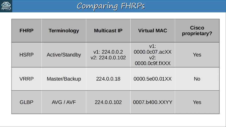
4.0 IP Services
NAT (Network Address Translation) is used to modify the source and/or destination IP addresses of packets.
There are various reasons to use NAT, but the most common reason is to allow hosts with private IP addresses to communicate with other hosts over the Internet.
Static NAT involves statically configuring one-to-one mappings of private IP addresses to public IP addresses. When traffic from the internal host is sent to the outside network, the router will translate the source address. However, this one-to-one mapping also allows external hosts to access the internal host via the inside global address.
An inside local IP address is mapped to an inside global IP address.
- Inside Local: The IP address of the inside host, from the perspective of the local network. (The IP address actually configured on the inside host, usually a private address)
- Inside Global: The IP address of the inside host, from the perspective of outside hosts (the IP address of the inside host after NAT, usually a public address)
- Outside Local: The IP address of the host on the outside network as seen from a host on the inside network
- Outside Global: The IP address configured on a host on the outside network
- Typically, NAT is configuredo nly for addresses on the inside network; therefore the outside local and global address are often identical.
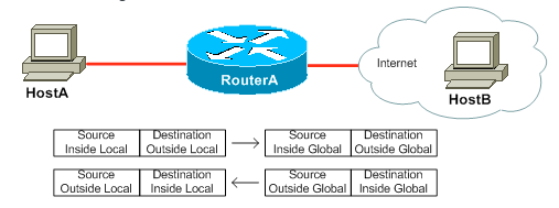
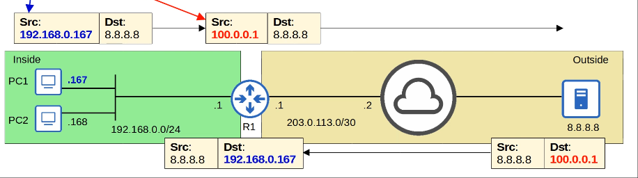
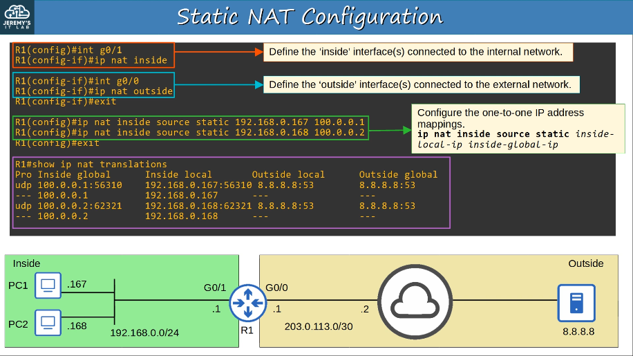
In dynamic NAT, the router dynamically maps inside local addresses to inside global addresses as needed.
An ACL is used to identify which traffic should be translated.
- If the source IP is permitted by the ACL, the soruce IP will be translated.
- If the source IP is denied by the ACL, the source IP will NOT be translated. (the traffic will NOT be dropped!)
A NAT pool is used to define the available inside global addresses that can be used.
Although they are dynamically assigned, the mappings are still one-to-one (one inside local IP address per inside global address)
If there arent enough inside global IP address available (=all are currently being used), it is called ‘NAT pool exhaustion’
- If a packet from another inside host arrives and needs NAT but there are no available addresses, the router will drop the packet.
- The host will be unable to access outside networks until one of the inside global IP addresses becomes available.
- Dynamic NAT entries will time out automatically if not used, or you can clear them manually.
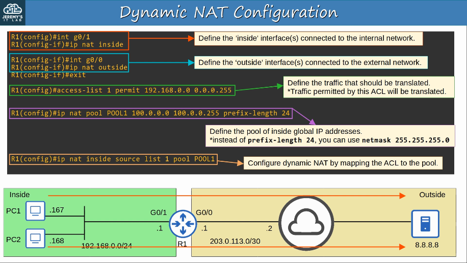
Nat commands:
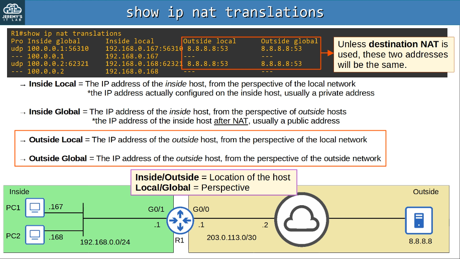
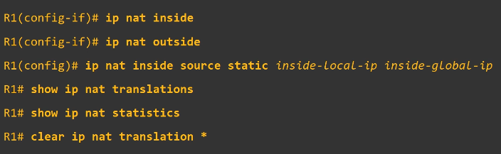
NTP (Network Time Protocol) allows automatic syncing of time over a network.
- NTP clients request the time from NTP servers.
- A device can be an NTP server and an NTP client at the same time.
- NTP allows accuracy of time within ~1 millisecond if the NTP server is in the same LAN, or within ~50 milliseconds if connecting to the NTP server over a WAN/the Internet.
- Some NTP servers are ‘better’ than others. The ‘distance’ of an NTP server from the orginal reference clock is called stratum.
- Reference clock is usually a very accurate time device like an atomic clock or a GPS clock.
- Reference clocks are stratum 0 within the NTP hierarchy. NTP servers directly connected to reference clocks are stratum 1 (primary servers). NTP servers that get their time from stratum 1 NTP servers are stratum 2 (secondary servers).
- Stratum 15 is the maximum.
- An NTP client can sync to multiple NTP servers.
- Devices can also ‘peer’ with devices at the same stratum to provide more accurate time. This is called ‘symmetric active’ mode.
- Cisco devices can operate in three NTP modes:
- Server mode
- Client mode
- Symmetric active mode
- NTP uses UDP port 123 to communicate.
- NTP uses only the UTC time zone. You must configure the appropriate time zone on each device.
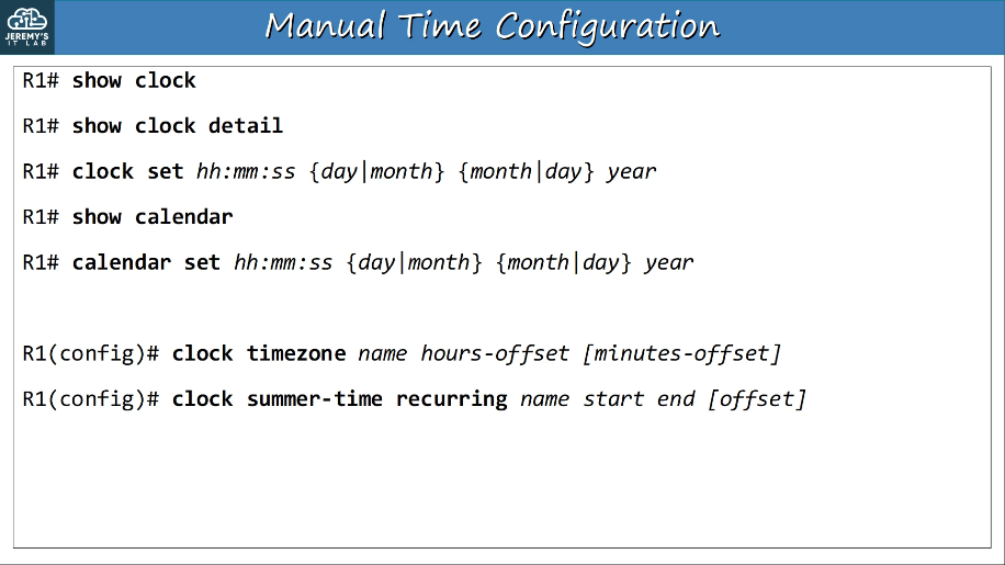
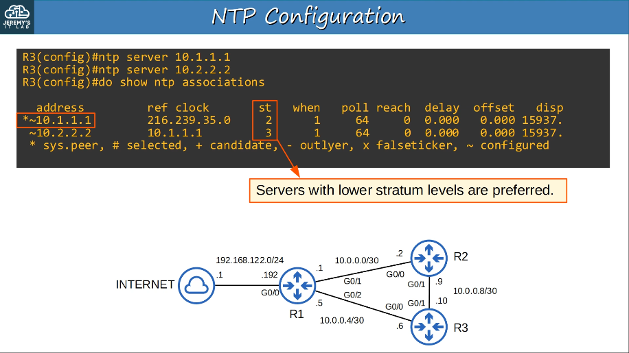
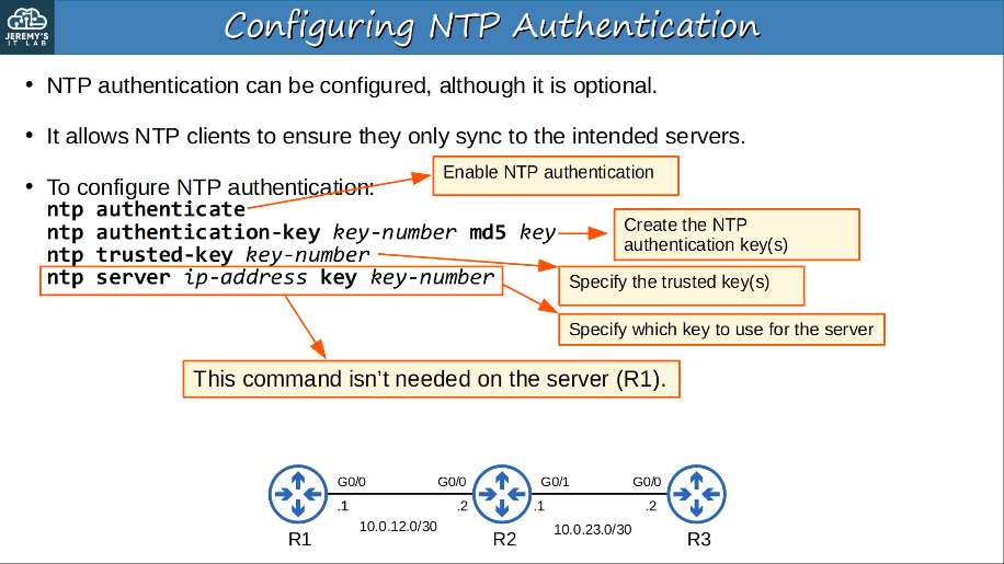
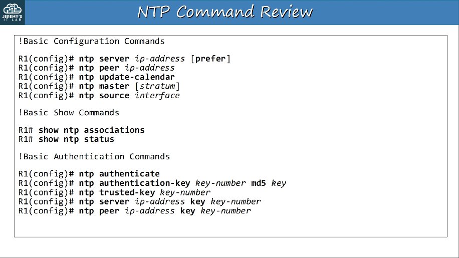
4.3 Explain the role of DHCP and DNS within the network
DNS (Domain Name System) is used to resolve human-readable names (google.com) to IP addresses.
When you type ‘youtube.com’ into a web browser, your device will ask a DNS server for the IP address of youtube.com.
The DNS server(s) your device uses can be manually configured or learned via DHCP.
Standard DNS queries/responses typically use UDP. TCP is used for DNS messages greater than 512 bytes. In either case, port 53 is used.
Devices will save the DNS server’s responses to a local DNS cache. This means they don’t have to query the server every single time they want to access a particular destination.
ipconfig /displaydns
nslookup youtube.com
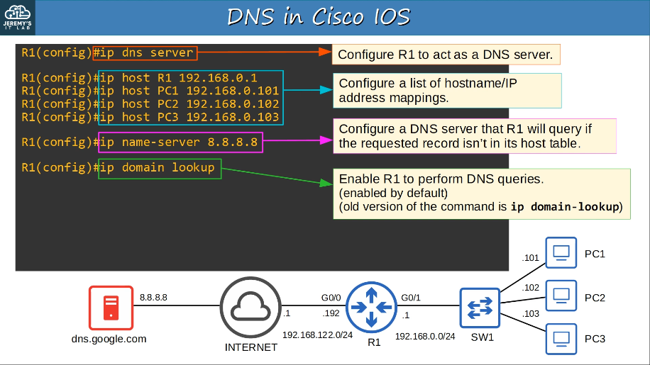
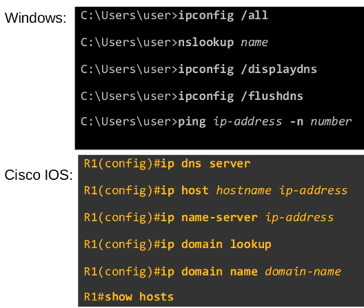
DHCP (Dynamic Host Configuration Protocol)
- DHCP is used to allow hosts to automatically/dynamically learn various aspects of their network configuration, such as IP address, subnet mask, default gateway, DNS server, etc, without manual/static configuration.
- It is an essential part of modern networks. Typically used for ‘client devices’ such as workstations (PCs), phones, etc.
- Devices such as routers, servers, etc, are usually manually configured.
- In small networks (such as home networks) the router typically acts as the DHCP server for hosts in the LAN.
- In larger networks, the DHCP server is usually a Windows/Linux server.
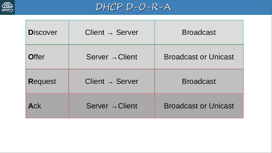
4.4 Explain the function of SNMP in network operations
SNMP (Simple Network Management Protocol) helps manage devices over a network.
Managed Devices are the devices being managed using SNMP, such as network devices (routers, switches, firewalls)
Network Management Stations (NMS) are the SNMP ‘servers’ that manage the devices.
- NMS receives notifications from managed devices
- NMS changes settings on managed devices
- NMS checks status of managed devices
Variables such as interface status, temperature, traffic load, host name, etc. are stored in the Management Information Base (MIB) and identified using Object IDs (OIDs)
Main SNMP versions: SNMPv1, SNMPv2c, SNMPv3
SNMP messages: Get, GetNext, GetBulk, Set, Trap, Inform, Response
There are three main operations used in SNMP.
- Managed devices can notify the NMS of events
- The NMS can ask the managed devices for information about their current status.
- The NMS can tell the managed devices to change aspects of their configuration.
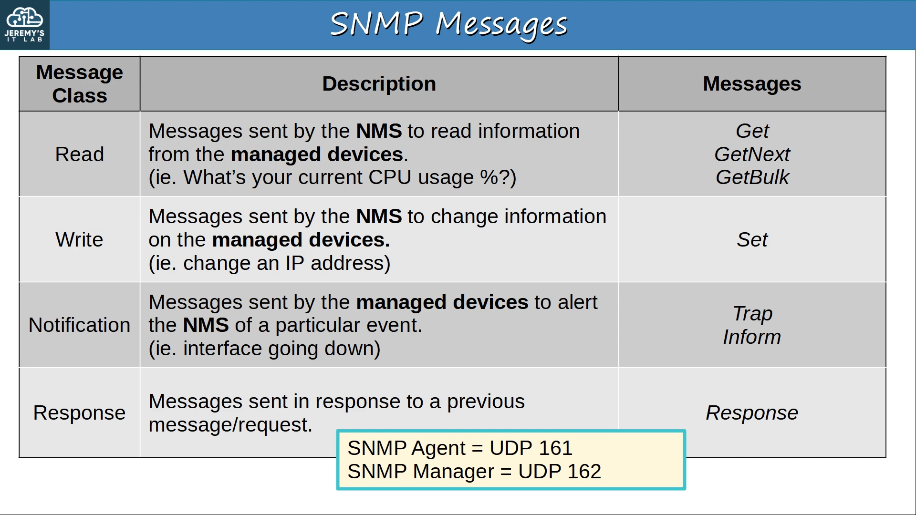
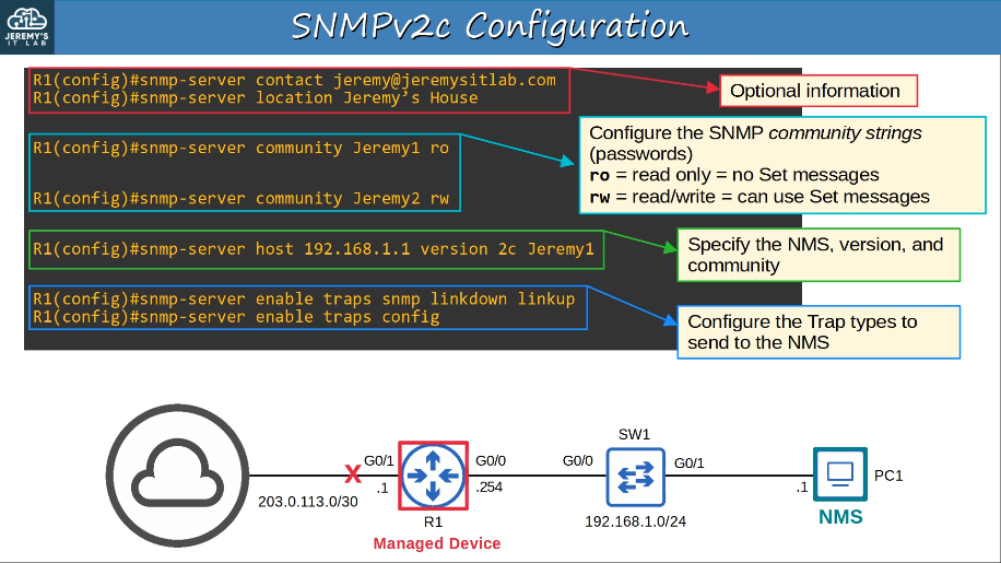
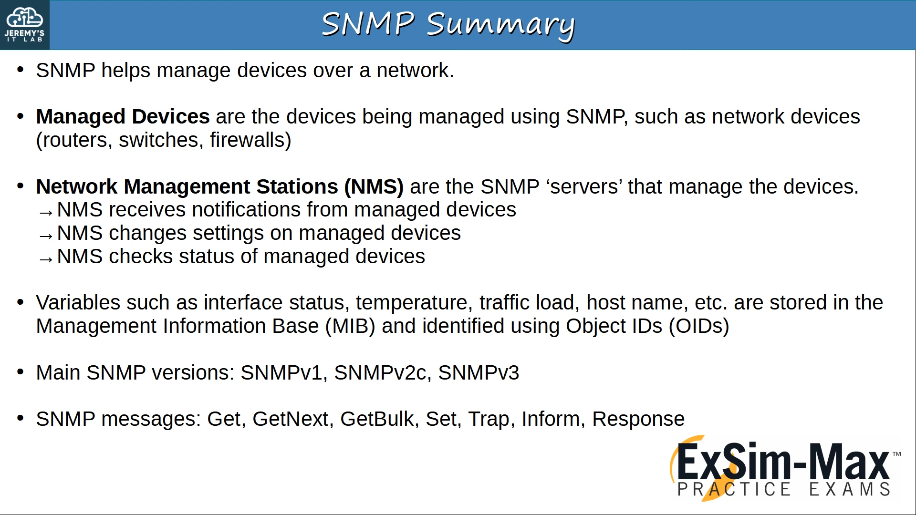
4.5 Describe the use of syslog features including facilities and levels
Syslog is an industry standard protocol for message logging.
On network devices, Syslog can be used to log events such as changes in interface status (up<->down), changes in OSPF neighbor status, system restarsts, etc.
The messages can be displayed in the CLI, saved in the device’s RAM, or sent to an external Syslog server.
Logs are essential when troubleshooting issues, examining the cause of incidents, etc.
Syslog and SNMP are both used for monitoring and troubleshooting of devices. They are complementary, but their functionalities are different.
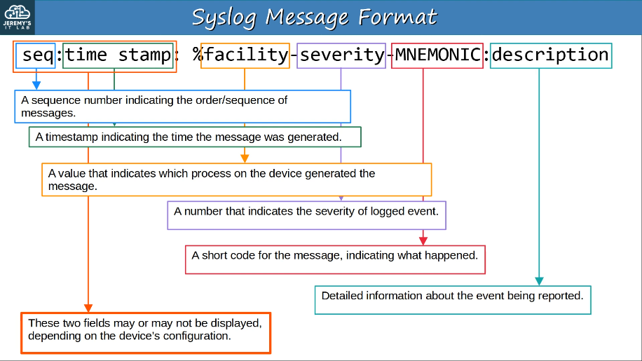
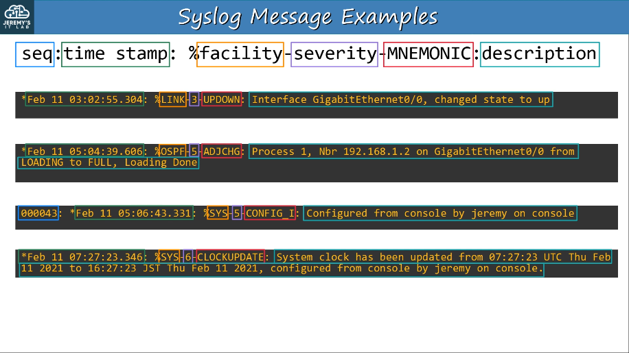
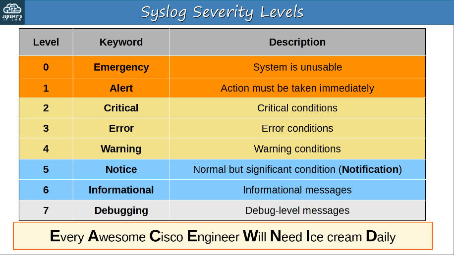
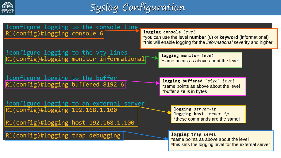
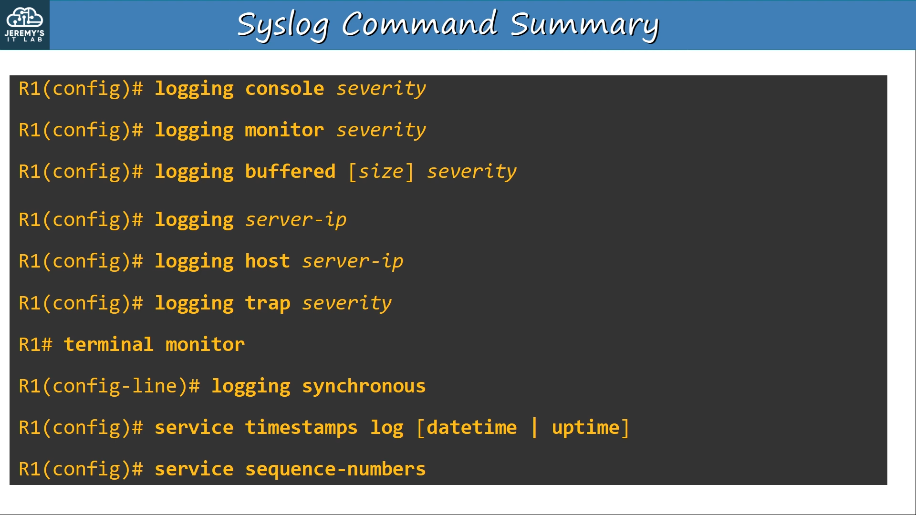
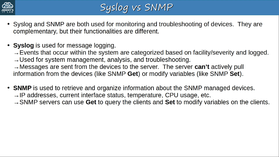
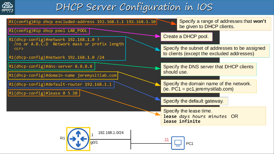
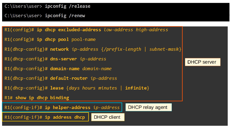
4.7 Explain the forwarding per-hop behavior (PHB) for QoS, such as classification, marking, queuing, congestion, policing, and shaping
- The purpose of QoS is to give certain kinds of network traffic priority over others during congestion.
- Classification organizes network traffic (packets) into traffic classes (categories)
- Classification is fundamental to QoS. To give priority to certain types of traffic, you have to identify which types of traffic to give priority to.
- There are many methods of classifying traffic. Some examples:
- An ACL. Traffic which is permitted by the ACL will be given certain treatments, other traffic will not.
- NBAR (Network Based Application Recognition) performs a deep packet inspection, looking beyond the Layer 3 and Layer 4 information up to Layer 7 to identify the specfific kind of traffic.
- In the Layer 2 and Layer 3 headers there are specific fields used for this purpose.
- The PCP (Priority Code Point) field of the 802.1Q tag (in the Ethernet header) can be used to identify high/low priority traffic.
- Only when there is a dot1q (VLAN) tag!
- PCP is also known as CoS (Class of Service). Its use is defined by IEEE (802.1p)
- 3 bits = 8 possible values (2^3 = 8)
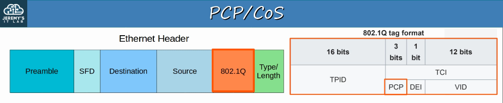
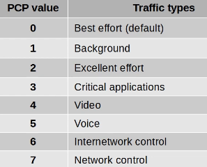
- ‘Best effort’ delivery means there is no guarantee that data is delivered or that it meets any QoS standard. This is regular traffic, not high-priority.
- IP phones mark call signaling traffic (used to establish calls) as PCP3.
- They mark the actual voice traffic as PCP5.
- Because PCP is found in the dot1q header, it can only be used over the following connections:
- trunk links
- access links with a voice VLAN
- The DSCP (Differentiated Services Code Point) field of the IP header can also be used to identify high/low priority traffic.
- IPP (IP Precedence) markings are similar to PCP, 8 values.
- 6 and 7 are reserved for ‘network control’ traffic. (ie. OSPF messages between routers)
- 5 = voice
- 4 = video
- 3 = voice signaling
- 0 = best effort
- With 6 and 7 reserved, 6 possible values remain.
- With IPP updated to DSCP, new standard markings had to be decided upon.
- Default Forwarding (DF) - best effort traffic
- The DSCP marking for DF is 0.
- Expedited Forwarding (EF) - low loss/latency/jitter traffic (usually voice)
- The DSCP marking for EF is 46.
- Assured Forwarding (AF) - A set of 12 standard values
- AF defines four traffic classes. All packets in a class have the same priority.
- Within each class, there are three levels of drop precedence.
- Higher drop precedence = more likely to drop the packet during congestion
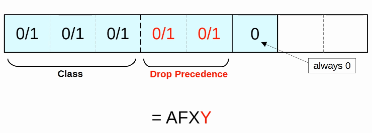 DSCP value = decimal value of the 6 bits.
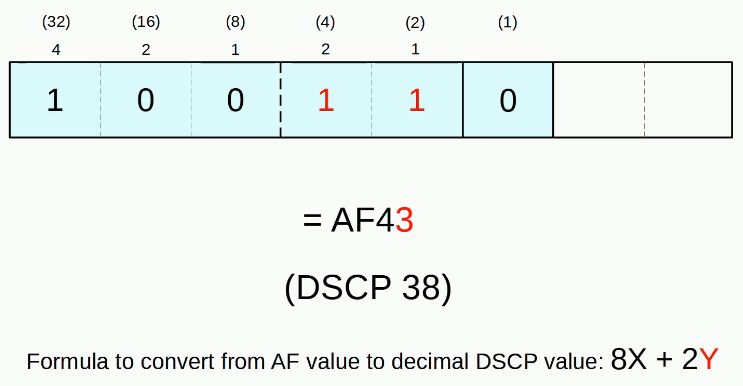
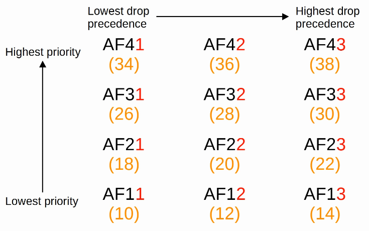
- Class Selector (CS) - A set of 8 standard values, provides backward compatibility with IPP
- The three bits that were added for DSCP are set to 0, and the original IPP bits are used to make 8 values.
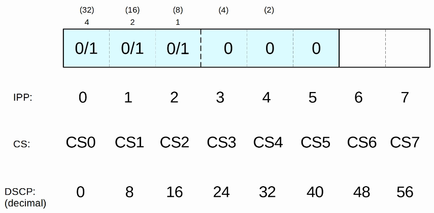
RFC 4954 was developed with the help of Cisco to bring all of these values together and standardize their use.
The RFC offers many specific recommendations, but here are a few key ones:
- Voice traffic: EF
- Interactive vide: AF4x
- Streaming video: AF3x
- High priority priority data: AF2x
- Best effort: DF
The trust boundary of a network defines where devices trust/don’t trust the QoS markings of received messages.
- If the markings are trusted, the device will forward the message without changing the markings.
- If the marking aren’t trusted, the device will change the markings according to the configured policy.
- If an IP phone is connected to the switch port, it is recommended to move the trust boundary to the IP phones.
- This is done via configuration on the switch port connected to the IP phones.
- If a user marks their PC’s traffic with a high priority, the marking will be changed (not trusted)
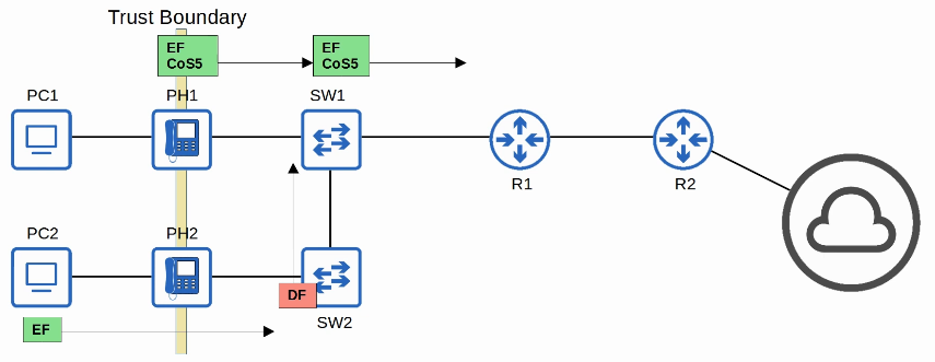
QoS is used to manage the following characteristics of network traffic:
- Bandwidth
- Delay
- Jitter
- Loss
The following standards are recommended for acceptable interactive audio quality:
- One-way delay: 150ms or less
- Jitter: 30 ms or less
- Loss: 1% or less
If a network device receives messages faster than it can forward them out of the appropriate interface, the messages are placed in a queue.
By default, queued messages will be forwarded in a First In First Out (FIFO manner)
- Messages will be sent in the order they are received.
If the queue is full new packets will be dropped, this is known as tail drop.
Tail drop is harmful because it can lead to TCP global synchronization causing all TCP hosts sending traffic to slow down the rate at which they send traffic, followed by all hosts increasing the rate at which they send traffic, rapidly leading to more congestion, dropped packets, and the process repeating again.
A solution to prevent tail drop and TCP global synchronization is Random Early Detected (RED).
- When the amount of traffic in the queue reaches a certain threshold, the device will start randomly dropping packets from select TCP flows.
- In standard RED, all kinds of traffic are treated the same.
- An improved version, WRED (Weighted Random Early Detection) allows you to control which packets are dropped depending on the traffic class (DSCP value) or IP precedence.
An essential part of QoS is the use of multiple queues.
- This is where classification plays a role. The device can match traffic based on various factors (for example the DSCP marking in the IP header) and then place it in the appropriate queue.
However, the device is only able to forward one frame out of an interface at once, so a scheduler is used to device which queue traffic is forwarded from next.
- Prioritization allows the scheduler to give certain queues more priority than others.
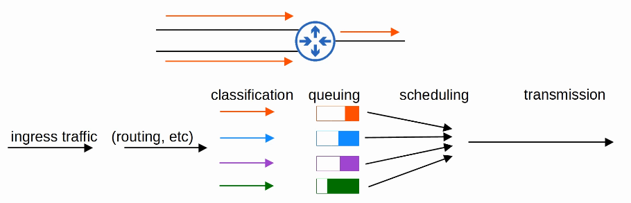
A common scheduling method is weighted round-robin.
- round-robin = packets are taken from each queue in order, cyclically
- weighted = more data is taken from high priority queues each time the scheduler reaches that queue.
CBQFQ (Class-Based Weighted Fair Queuing) is a popular method of scheduling, using a weighted round-robin scheduler while guaranteeing each queue a certain percentage of the interface’s bandwidth during congestion.
Round-robin scheduling is not ideal for voice/video traffic. Even if the voice/video traffic receives a guaranteed minimum amount of bandwidth, round-robin can add delay and jitter because even the high priority queues have to wait their turn in the scheduler.
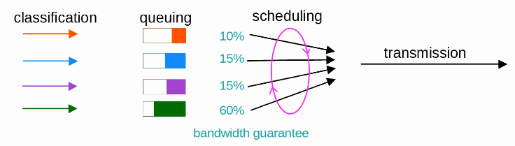
LLQ (Low Latency Queuing) designates one (or more) queues as strict priority queues.
- This means that if there is traffic in the queue, the scheduler will ALWAYS take the next packet from that queue unti it is empty.
This is very effective for reducing the delay and jitter of voice/video traffic.
However, it has the downside of potentially starving other queues if there is always traffic in the designated strict priority queue.
- Policing can control the amount of traffic allowed in the strict priority queue so that it can’t take all of the link’s bandwidth.
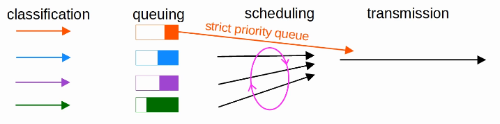
Traffic shaping and policing are both used to control the rate of traffic.
Shaping buffers traffic in a queue if the traffic rate goes over the configured rate.
Policing drops traffic if the traffic rate goes over the configured rate. (policing can also optionally re-mark the traffic instead of dropping)
- ‘Burst’ traffic over the configured rate is allowed for a short period of time.
- This accommodates data applications which typically are ‘bursty’ in nature. Instead of a constant stream of data, they send data in bursts.
- The amount of burst traffic allowed is configurable.
In both cases, classification can be used to allow for different rates for different kinds of traffic.
Example of why the rate traffic is being sent/received is being limited:
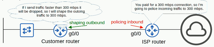
SSH (Secure Shell) allows for remote access while providing security features such as data encryption and authentication.
The SSH server (the device being connected to) listens for SSH traffic on TCP port 22.
To enable and use SSH, you must generate an RSA public and private key pair. The keys are used for data encryption/decryption, authentication, etc.
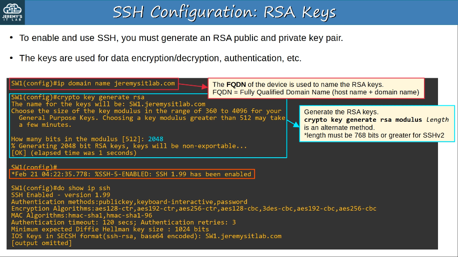
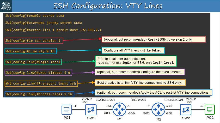
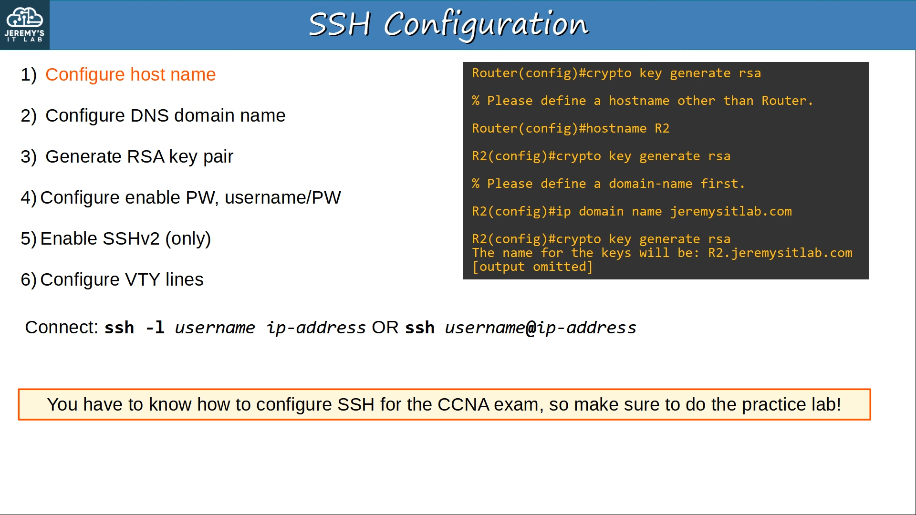
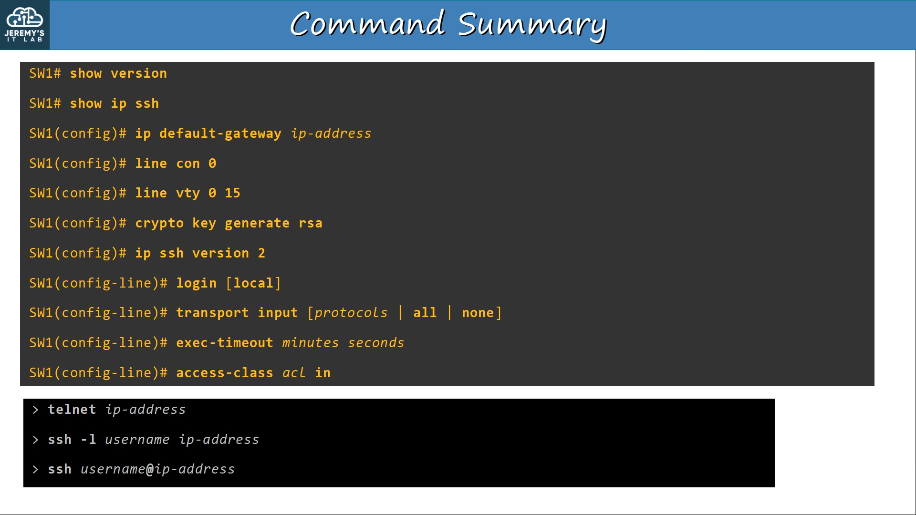
4.9 Describe the capabilities and function of TFTP/FTP in the network
FTP (File Transfer Protocol) and TFTP (Trivial File Transfer Protocol) are industry standard protocols used to transfer files over a network.
They both use a client-server model.
- Clients can use FTP or TFTP to copy files from a server.
- Clients can use FTP or TFTP to copy files to a server.
As a network engineer, the most common use for FTP/TFTP is in the process of upgrading the operating system of a network device. You can use FTP/TFTP to download the newer version of IOS from a server, and then reboot the device with the new IOS image.
FTP uses usernames and passwords for authentication, however there is no encryption.
- FTP uses TCP ports 20 and 21.
- For greater security, FTPS (FTP over SSL/TLS) can be used.
- SSH File Transfer Protocol (SFTP) can also be used for greater security (new protocol)
- FTP is more complex than TFTP and allows not only file transfers, but clients can also navigate file directories, add and remove directories, list files, etc.
- The client sends FTP commands to the server to perform these functions.
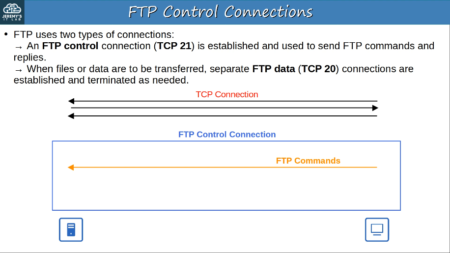
TFTP is named trivial because it is simple and has only basic features compared to FTP.
- Only allows a client to copy a file to or from a server.
- Released after FTP, but not a replacement for FTP. It is another tool to use when lightweight simplicity is more important than functionality.
- No authentication, servers will respond to all TFTP requests. No encryption, so all data is sent in plain text.
- Best used in a controlled environment to transfer small files quickly.
- TFTP servers listen on UDP port 69.
- UDP is connectionless and doesn’t provide reliability with retransmissions, however, TFTP has similar built-in features within the protocol itself.
- TFTP uses ‘lock-step’ communication. The client and server alternately send a message and then wait for a reply. (+retransmissions are sent as needed)
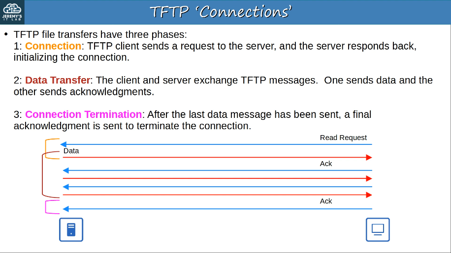
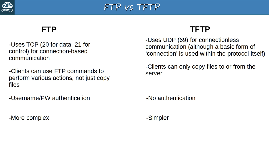
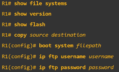
5.0 Security Fundamentals
The principles of the CIA Triad form the foundation of security:
Confidentiality
- only authorized users should be able to access data.
- some information/data is public and can be accessed by anyone, some is secret and should only be accessed by specific people.
Integrity
- Data should not be tampered with (modified) by unauthorized users.
- Data should be correct and authentic.
Availability
- The network/system should be operational and accessible to authorized users.
5.1 Define key security concepts (threats, vulnerabilities, exploits, and mitigation techniques)
A vulnerability is any potential weakness that can compromise the CIA of a system/info.
- a potential weakness isn’t a problem on its own
An exploit is something that can potentially be used to exploit the vulnerability.
- something that can potentially be used as an exploit isn’t a problem on its own
A threat is the potential of a vulnerability to be exploited.
- A hacker exploiting a vulnerability in your system is a threat.
A mitigation technique is something that can protect against threats.
- Should be implemented everywhere a vulnerability can be exploited: client devices. servers, switches, routers, firewalls, etc.
Common attacks:
- MAC spoofing
- An attacker uses the MAC address of another known host on the network in order to bypass port security measures. MAC spoofing can also be used to impersonate another host on the network. Implementing port security with sticky secure MAC addresses can help mitigate MAC spoofing attacks.
- MAC flooding
- An attacker generates thousands of forged frames every minute with the intention of overwhelming the switch’s MAC address table. Once this table is flooded, the switch can no longer make intelligent forwarding decisions and all traffic is flooded.
- This allows the attacker to view all data sent through the switch because all traffic will be sent out each port. Implementing port security can help mitigate MAC flooding attacks by limiting the number of MAC addresses that can be learned on each interface to a maximum of 128. A MAC flooding attack is also known as a Content Addressable Memory (CAM) table overflow attack.
- ARP poisoning
- Also known as an ARP (Address Resolution Protocol) spoofing attack, the attacker sends a gratuitous ARP (GARP) message to a host. The GARP message associates the attacker’s MAC address with the Internet Protocol (IP) addresses of a valid host on the network.
- Subsequently, traffic sent to the valid host address will go through the attacker’s computer rather than directly to the intended recipient. Implementing Dynamic ARP Inspection (DAI) can help mitigate ARP poisoning attacks. This is a man-in-the-middle style of attack.
- DHCP spoofing
- An attacker installs a rogue DHCP server on a network in an attempt to intercept DHCP requests. The rogue DHCP server can then respond to the DHCP requests with its own IP address as the default gateway address; hence all traffic is routing through the rogue DHCP server. You should enable DHCP snooping to help prevent DHCP spoofing attacks.
- VLAN hopping
- An attacker attempts to inject packets into other VLANs by accessing the VLAN trunk and double-tagging 802.1Q frames. A successful VLAN hopping attack enables an attacker to send traffic to other VLANs without the use of a router.
- You can prevent VLAN hopping by disabling Dynamic Trunking Protocol (DTP) on trunk ports, by changing the native VLAN, and by configuring user-facing ports as access ports.
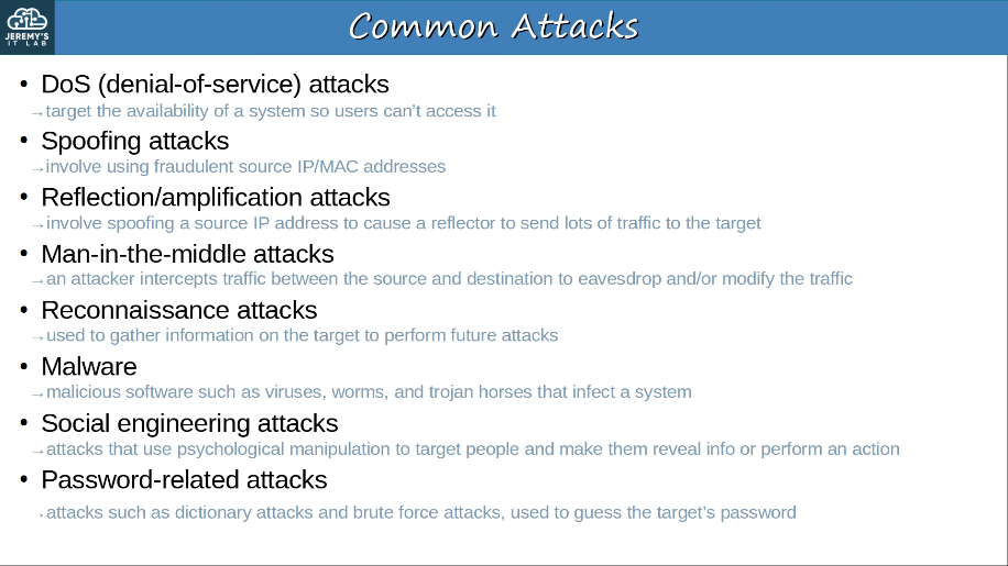
5.2 Describe security program elements (user awareness, training, and physical access control)
User awareness programs are designed to make employees aware of potential security threats and risks.
- For example, a company might send out false phishing emails to make employees click a link and sign in with their login credentials.
- Although the emails are harmless, employees who fall for the false emails will be informed that it is part of a user awareness program and they should be more careful about phishing emails.
User training programs are more formal than user awareness programs.
- For example, dedicated training sessions which educate users on the corporate secuirty policies, how to create strong passwords, and how to avoid potential threats.
Physical access control protects equipment and data from potential attackers by only allowing authorized users into protected areas such as network closets or data center floors.
- Multifactor locks can protect access to restricted areas.
- ie. a door that requires users to swipe a badge and scan their fingerprint to enter.
- Permissions of the badge can easily be changed, for example permissions can be removde when an employee leaves the company.
5.4 Describe security password policies elements, such as management, complexity, and password alternatives (multifactor authentication, certificates, and biometrics)
Multi-factor authentication involves providing more than just a username/password to prove your identity. It usually involves providing two (or more) of the following:
- Something you know
- a username/password combination, a PIN, etc.
- Something you have
- pressing a notification that appears on your phone, a badge that is scanned, etc.
- Something you are
- biometrics such as a face scan, palm scan, fingerprint scan, retina scan, etc.
Requiring multiple factors of authentication greatly increases the security.
Digital certificates are another form of authentication used to prove the identity of the holder of the certificate. They are used for websites to verify that the website being accessed is legitimate.
Entities that want a certificate to prove their identity send a CSR (Certificate Signing Request) to a CA (Certificate Authority), which will generate and sign the certificate.
5.5 Describe IPsec remote access and site-to-site VPNs
To provide secure communications over the Internet, VPNs (Virtual Private Networks) are used. We will cover two kinds of Internet VPNs:
- Site-to-Site VPNs using IPsec
- Remote-access VPNs using TLS
Site-to-Site VPNs (IPsec)
- A site-to-site VPN is a VPN between two devices and is used to connect two sites together over the Internet.
- A VPN ‘tunnel’ is created between the two devices by encapsulating the original IP packet with a VPN header and a new IP header.
- When usuing IP sec, the original packet is encrypted before being encapsulated with the new header.
- provides data confidentiality, data integrity, and origin authentication.
- IPsec uses Encapsulating Security Protocol (ESP) to provide data confidentiality. ESP encrypts an entire IP packet and encapsulates it as the payload of a new IP packet. Because the entire IP packet is encrypted, the data payload and header information remain confidential.
- In additon, IPsec uses Authentication Header (AH) to ensure the integrity of a packet and to authenticate the origin of a packet. AH does not authenticate the identity of an IPsec peer; instead, AH verifies only that the source address in the packet has not been modified during transit.
Site-to-site VPNs:
.png)
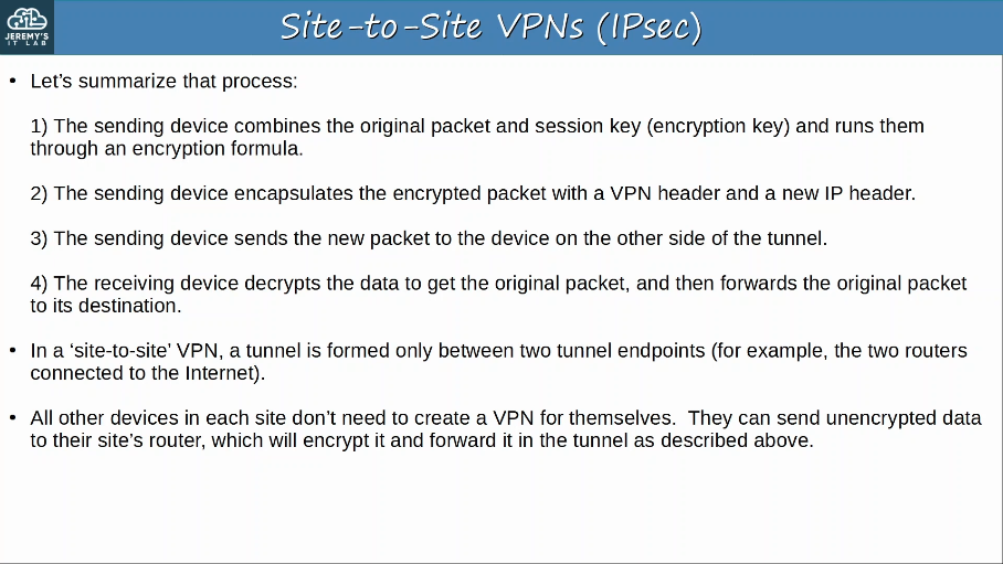
There are some limitations to standard IPsec:
IPsec doesn’t support broadcast and multicast traffic, only unicast. This means that routing protocols such as OSPF can’t be used over the tunnels, because they rely on multicast traffic.
- This can be solved with ((‘GRE over IPsec’(())
- GRE (Generic Routing Encapsulation) creates tunnels like IPsec, however it does not encrypt the original packet, so it is not secure.
- However, it has the advantage of being able to encapsulate a wide variety of Layer 3 protocols, including broadcast and multicast messages.
- To get the flexibility of GRE with the security of IPsec, ‘GRE over IPsec’ can be used.
- The original packet will be encapsulated by a GRE header and a new IP header, and then the GRE packet will be encrypted and encapsulated within an IPsec VPN header and new IP header.
- GRE can tunnel traffic from one network to another without requiring the transport network to support the network protocols in use at the tunnel source or tunnel destination.
- Because the focus of GRE is to transport many different protocols, it has very limited security features.
- By contrast IPsec has strong data confidentiality and data integrity features but it can transport only IP traffic. GRE over IPsec combines the best features of both protocols to securely transport any protocol over an IP network.
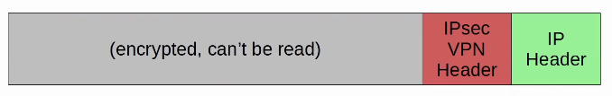
Configuring a full mesh of tunnels between many sites is a labor-intesive task.
- This can be solved with Cisco’s DMVPN.
- DMVPN (Dynamic Multipoint VPN) is a Cisco-developed solution that allows routers to dynamically create a full mesh of IPsec tunnels without having to manually configure every single tunnel.
- DMVPN provides the configuration simplicity of hub-and-spoke (each spoke router only needs one tunnel configured) and the efficiency of direct spoke-to-spoke communication (spoke routers can communicate directly without traffic passing through the hub)
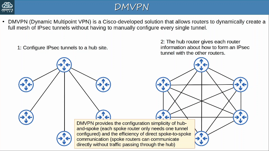
Remote-Access VPNs
- Whereas site-to-site VPNs are used to make a point-to-point connection between two sites over the Internet, remote-access VPNs are used to allow end devices (PC, mobile phones) to access the company’s internal resources securely over the Internet.
- Remote-access VPNs typically use TLS (Transport Layer Security)
- TLS is also what provides security for HTTPS (HTTP Secure)
- TLS was formerly known as SSL (Secure Sockets Layer) and developed by Netscape, but was renamed to TLS when it was standardized by the IETF.
- VPN client software (for example Cisco AnyConnect) is installed on en end devices (for example company-provided laptops that employees work from home).
- These end devices then form secure tunnels to one of the company’s router/firewalls acting as a TLS server.
- This allows the end users to securely access resources on the company’s internal network without being directly connected to the company network.
Remote-Access VPNS:
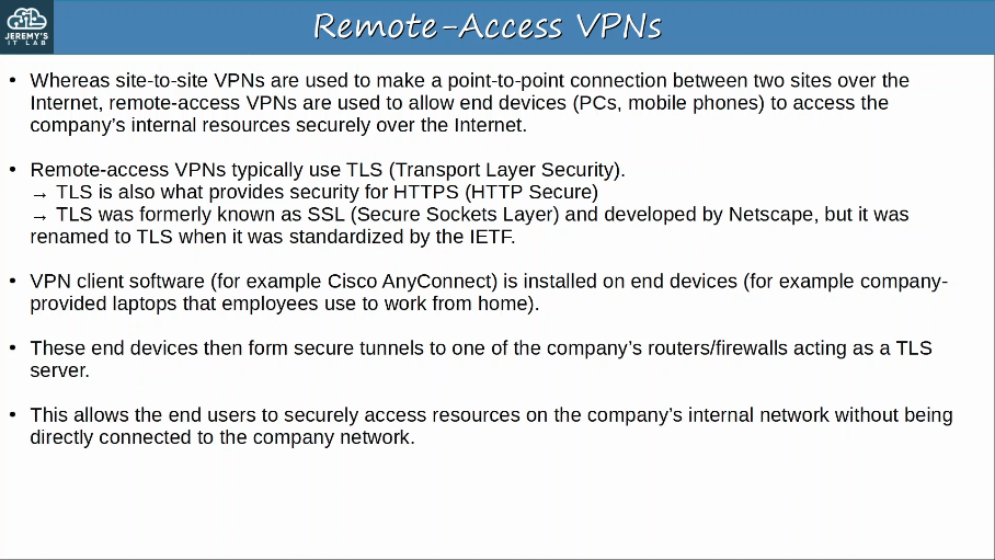
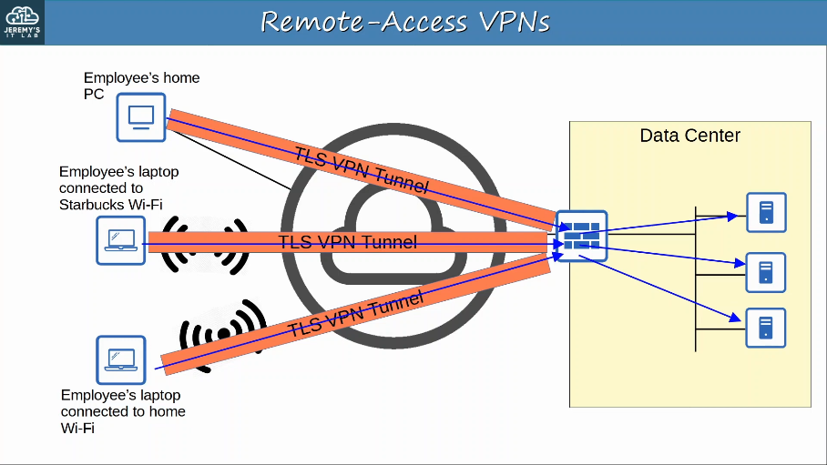
Site-to-Site vs Remote-Access VPN
- Site-to-Site VPNs typically use IPsec.
- Remote-Access VPNs typically use TLS.
- Site-to-Site VPNs provide service to many devices within the sites they are connecting.
- Remote-Access VPNs provide service to the one end device the VPN client software is installed on.
- Site-to-Site VPNs are typically used to permanently connect two sites over the Internet.
- Remote-Access VPNs are typically used to provide on-demand access for end devices that want to securely access company resources while connected to a network which is not secure.
ACLs (Access Control Lists) function as a packet filter, instructing the router to permit or discard specific traffic.
ACLs can filter traffic based on source/destination IP addresses, source/destination IP addresses, source/destination Layer 4 ports, etc.
ACLs are configured globally on the router, and consist of an ordered sequence of ACEs (Access Control Entries)
Configuring an ACL will not make the ACL take effect, the ACL must be applied to an interface. ACLs are applied either inbound or outbound.
If the packet matches one of the ACEs in the ACL, the router takes the action and stops processing the ACL, all entries below the matching entry will be ignored.
There is an implicit deny at the end of all ACLs. The implicit deny tells the router to deny all traffic that doesn’t match any of the configured entries in the ACL.
Standard ACLs: Match based on the Source IP address only.
- Standard ACLs can use 1-99 and 1300-1999.
- Standard ACLs should be applied as close to the destination as possible.
- R1(config)# access-list (#) (deny/permit) (ip) (wildcard-mask)
R1(config-if)# ip access-group (#) (in/out)
Extended ACLs: Match based on Source/Destination IP, Source/Destination port/protocol, etc
- Extended ACLs can use 100-199, 2000-2699.
- Extended ACLs should be appleid as close to the source as possible.
R1(config)# access-list (#) (permit/deny) (protocol) (src-ip) (dest-ip)
R1(config)# ip access-list extended (name/number)
R1(config-ext-nacl)# (seq-num) (permit/deny) (protocol) (src-ip) (dest-ip)
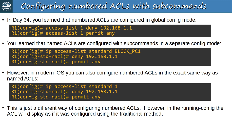
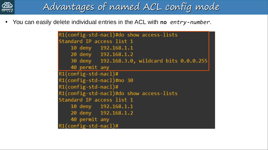
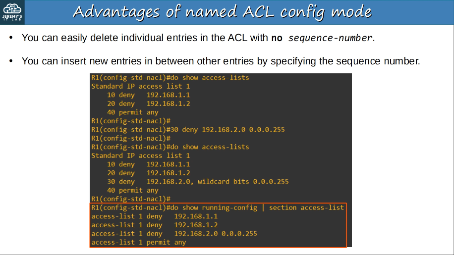
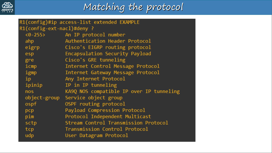
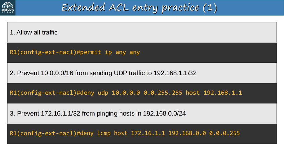
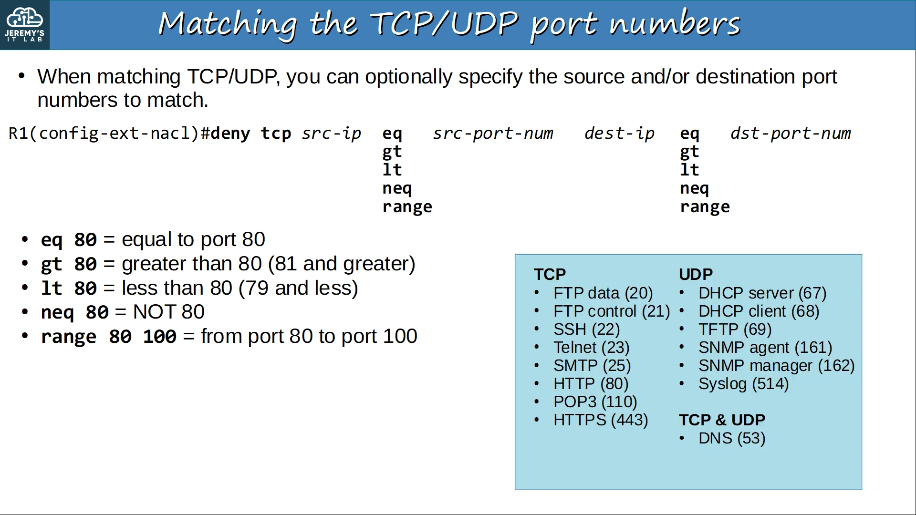
DHCP snooping is security feature of switches that is used to filter DHCP messages received on untrusted ports.
DHCP snooping only filters DHCP messages. Non-DHCP messages aren’t affected.
All ports are untrusted by default.
- Usually, uplink ports are configured as trusted ports, and downlink ports remain untrusted.
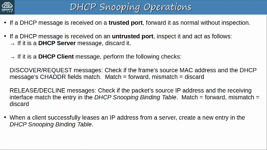
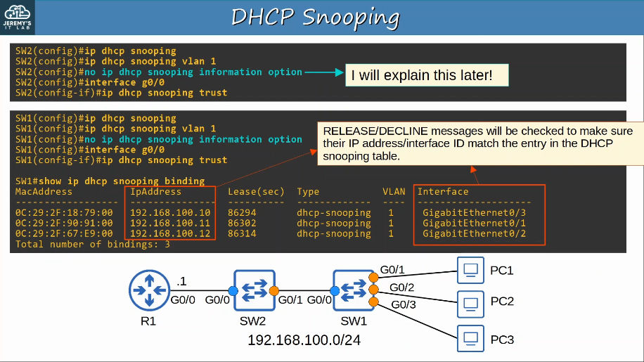
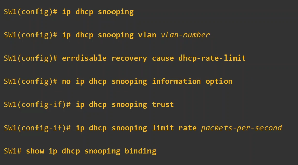
Dynamic ARP inspection (DAI) is a security feature of switches that is used to filter ARP messages received on untrusted ports.
DAI only filters ARP messages. Non-ARP messages aren’t affected.
All ports are untrusted by default.
- Typically, all ports connected to other network devices (switches, routers) should be configured as trusted, while itnerfaces connected to end hosts should remain untrusted.
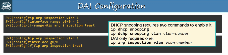
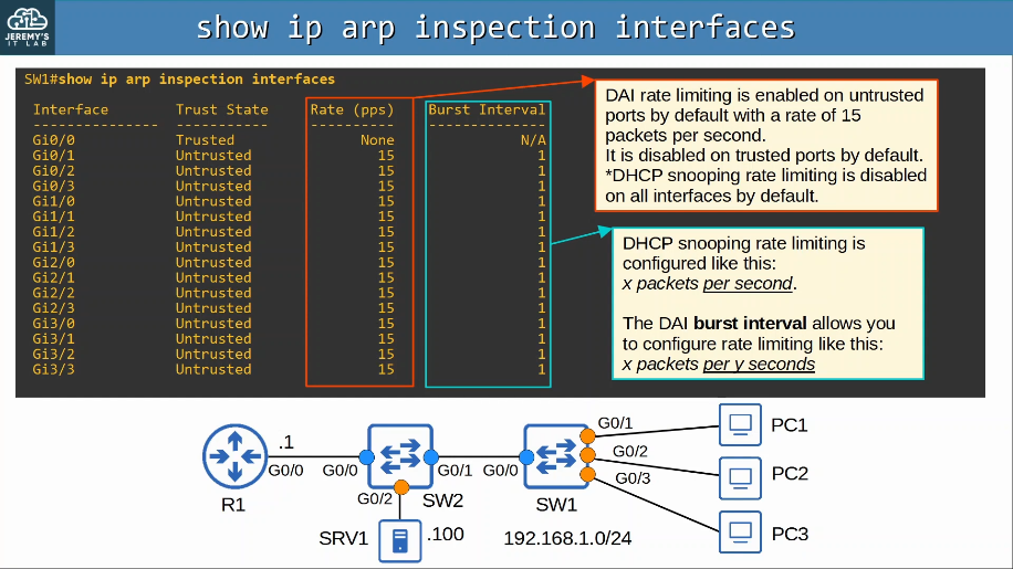
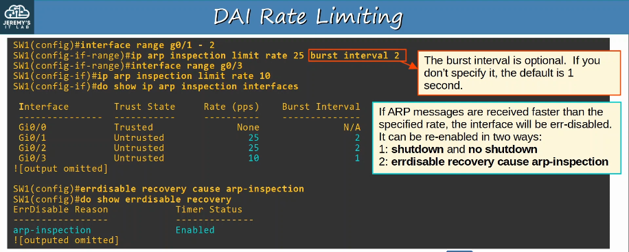
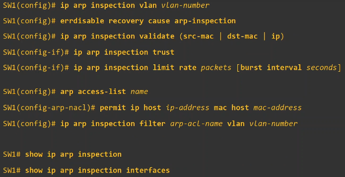
Port security is a security feature of Cisco switches. It allows you to control which source MAC address(es) are allowed to enter the switchport.
If an authorized source MAC address enters the port, an action will be taken.
- The default action is to place the interface in an ‘err-disabled’ state.
When you enable port security on an interface with the default settings, one MAC Addres is allowed.
- You can configure the allowed MAC address manually.
- If you don’t configure it manually, the switch will allow the first source MAC address that enters the interface.
- You can change the maximum number of MAC addresses allowed
- A combination of manually configured MAC addresses and dynamically learned addresses is possible.
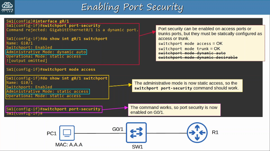
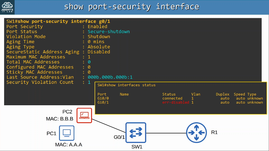
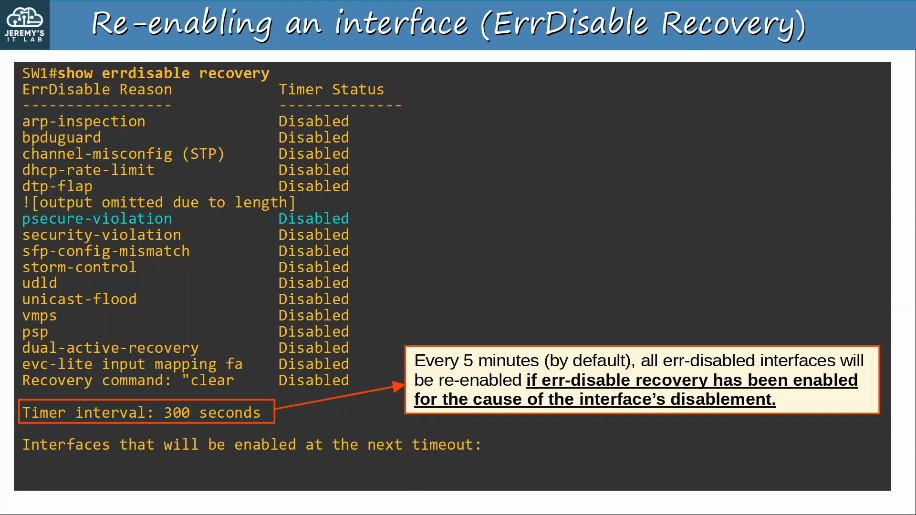
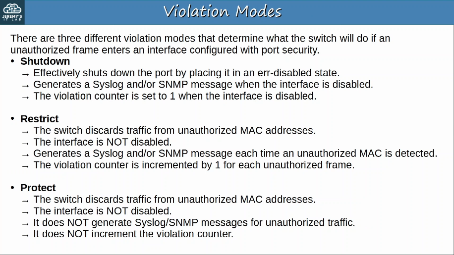
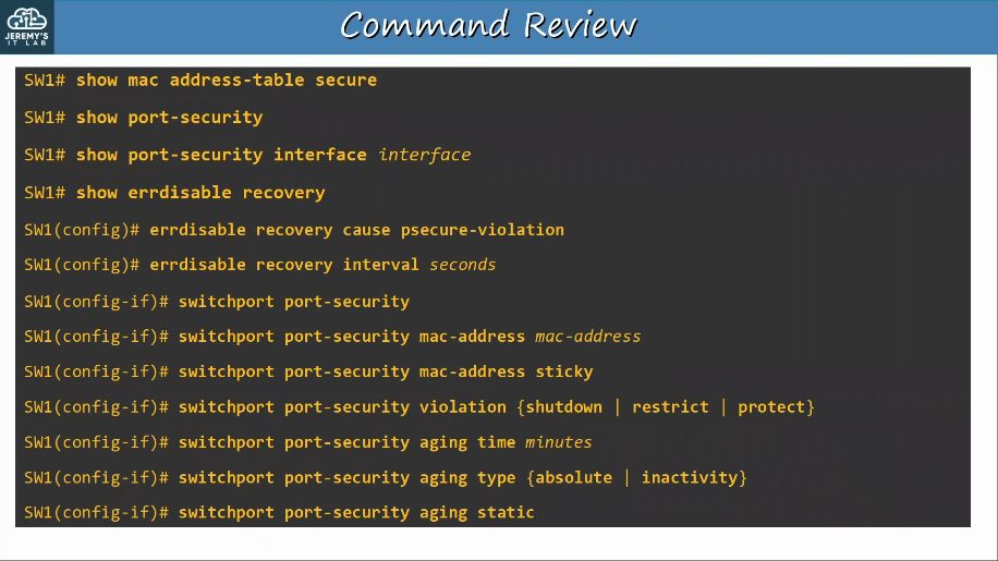
5.8 Compare authentication, authorization, and accounting concepts
AAA (triple-A) stands for Authentication, Authorization, and Accounting.
It is a framework for controlling and monitoring users of a computer system (ie. a network)
Authentication is the process of verifying a user’s identity.
- logging in = authentication
Authorization is the process of granting the user the appropriate access and permissions.
- granting the user acces to some files/services, restricting access to other files/services = authorization.
Accounting is the process of recording the user’s activities on the system.
- logging when a user makes a change to a file = accounting
5.9 Describe wireless security protocols (WPA, WPA2, and WPA3)
The Wi-Fi alliance has developed three WPA certifications for wireless devices:
To be WPA-certified, equipment must be tested in authorized testing labs.
All of the above support two authentication modes:
- Personal mode: A pre-shared key (PSK) is used for authentication. When you connect to a home Wi-Fi network, enter the password and are authenticated, that is personal mode. This is common in small networks. The PSK itself is not sent over the air. A four-way handshake is used to generate encryption keys.
- Enterprise mode: 802.1X is used with an authentication server (RADIUS server). *No specific EAP method is specified, so all are supported (PEAP, EAP-TLS, etc).
The WPA certification was developed after WEP was proved to be vulnerable and includes the following protocols:
- TKIP (based on WEP) provides encryption/MIC
- 802.1X authentication (Enterprise mode) or PSK (Personal mode)
WPA2 was released in 2004 and includes the following protocols:
- CCMP provides encryption/MIC.
- 802.1X authentication (Enterprise mode) or PSK (Personal mode)
WPA3 was released in 2018 and includes the following protocols:
- GCMP provides encryption/MIC
- 802.1X authentication (Enterprise mode) or PSK (Personal mode)
- WPA3 also provides serveral additional security features, for example:
- PMF (Protected Management Frames), protecteing 802.11 management frames from eavesdropping/forging.
- SAE (Simulataneous Authentication of Equals) protects the four-way handshake when using personal mode authentication.
- Forward secrecy prevents data from being decrypted after it has been transmitted over the air, to prevent an attacker from capturing wireless frames and then trying to decrypt them later.
6.0 Automation and Programmability
There are various tools/methods that can be used to automate tasks in the network:
- SDN (Software-Defined Networking)
- Ansible
- Puppet
- Python scripts, etc
6.1 Explain how automation impacts network management
Network automation provides many key benefits:
- Human error (typos etc.) is reduced.
- Network become much more scalable. New deployments, network-wide changes, and troubleshooting can be implemetned in a fraction of time.
- Network-wide policy compliance can be assured (standard configurations, software versions, etc).
- The improved efficiency of network operations reduces the opex (operating expenses) of the network. Each task requires fewer man-hours.
6.2 Compare traditional networks with controller-based networking
In traditional networking, the data plane and control plane are both distributed. Each device has its own data plane and its own control plane. The planes are ‘distributed’ throughout the network.
Networking tasks can be automated in tradition network architectures too:
- Scripts can be written (ie. using Python) to push commands to many devices at once
- Python with good use of Regular Expression can parse through show commands to gather infromation about the network devices.
However, the robust and centralized data collected by SDN controllers greatly facilitates these functions.
- The controller collects information about all devices in the network.
- Northbound APIs allows apps to access information in a format that is easy for programs to understand (ie. JSON, XML)
- The centralized data facilitates network-wide analytics.
SDN tools can provide the benefits of automation without the requirement of third-party scripts & apps.
- You don’t need expertise in automation to make use of SDN tools.
- However, APIs allow third-party applications to interact with the controller, which can be very powerful.
Although SDN and automation aren’t the same thing, the SDN architecture greatly facilitates the automation of various tasks in the network via the SDN controller and APIs.
6.3 Describe controller-based, software defined architecture (overlay, underlay, and fabric)
SDN (Software-Defined Networking) is an approach to networking that centralizes the control plane into an application called a controller.
SDN is also called the Software-Defined Architecture (SDA) or Controller-Based Networking.
Traditional control planes use a distributed architecture.
- For example, each router in the network runs OSPF and the routers share routing information and then calculate their preferred routers to each destination.
An SDN controller centralizes control plane functions like calculating routes (EIGRP, OSPF).
- That is just an example, and how much of the control plane is centralized varies greatly.
The controller can interact programmatically with the network devices using APIs (Application Programming Interface)
The SBI is used for communications between the controller and the network devices it controls.
The NBI is what allows us to interact with the controller with our scripts and applications.
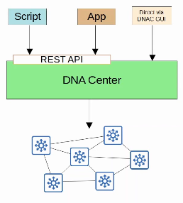
- The underlay is the underlying physical network of devices and connections (including wired and wireless) which provide IP connectivity (ie. using IS-IS).
- Multilayer switches and their connections
- The overlay is the virtual network built on top of the physical underlay network.
- SD-Access uses VXLAN (Virtual Extensible LAN) to build tunnels
- The fabric is the combination of the overlay and underlay; the physical and virtual network as a whole.
SD-Access Underlay
- The underlay’s purpose is to support the VXLAN tunnels of the overlay.
- There are three different roles for switches in SD-Access:
- Edge nodes: Connect to end hosts
- Border nodes: Connect to devices outside of the SD-Access domain, ie. WAN routers
- Control nodes: Use LISP (Locator ID Seperation Protocol) to perform various control plane functions.
- You can add SD-Access on top of an existing network (brownfield deployment) if your network hardware and software supports it.
- Google ‘Cisco SD-Access compatibility matrix’ if you’re curious.
- In this case DNA Center won’t configure the underlay.
- A new deployment (greenfield deployment) will be configured by DNA Center to use the optimal SD-Access underlay:
- All switches are Layer 3 and use IS-IS as their routing protocol.
- All links between switches are router ports. This means STP is not needed.
- Edge nodes (access switches) act as the default gateway of end hosts (routed acces layer)
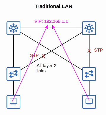
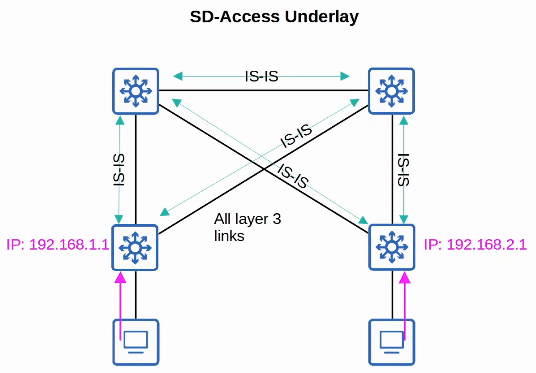
SD-Access Overlay
LISP provides the control plane of SD-Access
- A list of mappings of EID (endpoint identifiers) to RLOCs (routing locations) is kept.
- EIDs identify end hosts connected to edge switches, and RLOCs identify the edge switch which can be used to reach the end host.
- There is a LOT more detail to cover about LISP, but this is just to show how it differs form the traditional control plane.
Cisco TrustSec (CTS) provides policy control (QoS, security policy, etc. VXLAN provides the data plane of SD-Access.
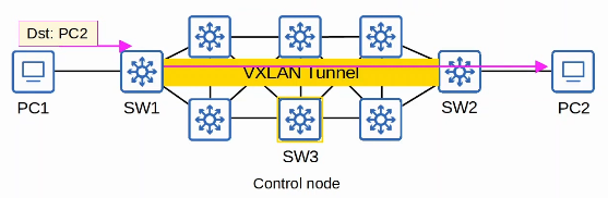
6.3.a Seperation of control plane and data plane
The various functions of network devices can be logically divided up (categorized) into planes:
Data plane
- All tasks involved in forwarding user data/traffic from one interface to another are part of the data plane.
- A router receives a message, looks for the most specific matching route in its routing table, and forwards it out of the appropriate interface to the next hop.
- It also de-encapsulates the original Layer 2 header, and re-encapsulates with a new header destined for the next hop’s MAC address.
- A switch receives a message, looks at the destination MAC address, and forwards it out of the appropriate interface (or floods it).
- This includes functions like adding or removing 802.1q VLAN tags.
- NAT (changing the src/dst addresses before forwarding) is part of the data plane.
- Deciding to forward or discard messages due to ACLs, port security, etc. is part of the data plane.
- The data plane is also called the ‘forwarding plane’.
- Layer 2 switches, layer 3 switches, and end devices typically operate in the data plane.
- Network tasks that are typically performed in the data plane include the encapsulation and decapsulation of packets, the adding or removing of trunk headers, the matching of MAC addresses to a MAC address table, the matching of IP addresses to paths in a routing table, the encryption of data, NAT, and filtering by using either ACLs or port security.
Control plane
- How does a device’s data plane make its forwarding decisions?
- routing table, MAC address table, ARP table, STP, OSPF, EIGRP etc.
- Functions that build these tables (and other functions that influence the data plane) are part of the control plane.
- The control plane controls what the data plane does, for example by building the router’s routing table.
- The control plane performs overhead work.
- OSPF itself doesn’t forward user data packets, but it informs the data plane about how packets should be forwarded.
- STP itself isn’t directly involved in the process of forwarding frames, but it informs the data plane about which interfaces should and shouldn’t be used to forward frames.
- ARP messages aren’t user data, but they are used to build an ARP table which is used in the process of forwarding data.
- In a traditional network, the control plane is typically dsitributed among many devices (ex. OSPF)
- In a controller-based network, the decision-making logic is either moved to a central controller or monitored by a central controller.
Management plane
- Like the control plane, the management plane performs overhead work.
- However, the management plane doesn’t directly affect the forwarding of messages in the data plane.
- The management plane consists of protocols that are used to manage devices.
- SSH/Telnet, used to connect to the CLI of a device to configure/manage it.
- Syslog, used to keep logs of events that occur on the device.
- SNMP, used to monitor the operations of the device.
- NTP, used to maintain accurate time on the device.
When a device received control/management traffic (destined for itself), it will be processed in the CPI.
When a device receives data traffic which should pass through the device, it is processed by the ASIC for maximum speed.
6.3.b Northbound and Southbound APIs
The SBI (Southbound Interface) is used for communications between the controller and the network devices it controls. Southbound APIs enable an SDN controller to communicate with devices in the data plane.
It typically consists of a communication protocol and API (Application Programming Interface).
APIs facilitate data exchanges between programs.
- Data is exchanged inbetween the controller and the network devices.
- An API on the network devices allows the controller to access information on the devices, control their data plane tables, etc
Some examples of SBI’s are: OpenFlow, Cisco OpFlex, Cisco onePK (Open Network Environment Platform Kit), NETCONF
Using the SBI, the controller communicates with the managed devices and gathers information about them:
- The devices in the network
- The topology (how the devices are connected together)
- the available interfaces on each device
- their configurations
The NBI (Northbound Interface) is what allows us to interact with the controller, access the data it gathers about the network, program it, and make changes in the network via the SBI.
Northbound APIs enable an SDN controller to communicate with applications in the application plane. The application plane is a component of a controller-based network in which applications that are written to allow interaction with the centralized controller reside.
Applications use northbound APIs (REST, OSGi) to send requests or instructions to the SDN controller, which uses that information to modify and manage network flow/manage network efficiency.
A REST (Representational State Transfer) API is used on the controller as an interface for apps to interact with it.
Data is sent in a structure (serialized) format such as JSON or XML.
- This makes it much easier for programs to use the data.
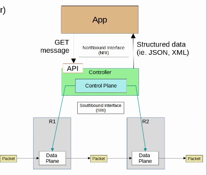
6.4 Compare traditional campus device management with Cisco DNA Center enabled device management
Cisco SD-Access is Cisco’s SDN solution for automating campus LANs.
- ACI (Application Centric Infrastructure) is their SDN solution for automating data center networks.
- SD-WAN is their SDN solution for automating WANs
- Cisco DNA (Digital Network Architecture) Center is the controller at the center of SD-Access.
Cisco DNA Center has two main roles
- The SDN controller in SD-access
- A network manager in a traditional network (non-SD-Access)
DNA Center is an application installed on Cisco UCS server hardware.
- It has a REST API which can be used to interact with DNA center.
- The SBI supports protocols such as NETCONF and RESTCONF (as well as traditional protocols like Telnet, SSH, SNMP)
- DNA Center enables Intent-Based Networking (IBN).
- The goal is to allow the engineer to communicate their intent for network behavior to DNA Center, and then DNA Center will take care of the details of the actual configurations and policies on devices.
Traditional security policies using ACLs can become very cumbersome.
- ACLs can have thousands of entries.
- The intent of entries is forgotten with time and as engineers leave and new engineers take over.
- Configuring and applying the ACLs correctly across a network is cumbersome and leaves room for error.
- DNA Center allows the engineer to specify the internet of the policy (this group of users can’t communicate with this grup, this group can access this server but not that server, etc) and DNA Center will take care of the exact details of implementing the policy.
Traditional network management:
- Devices are configured one-by-one via SSH or console connection
- Devices are manually configured via console connection before being deployed
- Configurations and policies are managed per-device (distributed)
- New network deployments can take a long time due to the manual labor required
- Errors and failures are more likely due to increased manual effort.
DNA Center-based network management:
- Devices are centrally managed and monitored from the DNA Center GUI or other applications using its REST API.
- The administrator communicates their intended network behavior to DNA Center, which changes those intentions into configurations on the managed network deivces.
- Configurations and policies are centrally manaaged.
- Software versions are also centrally managed. DNA Center can monitor cloud servers for new versions and then update the manged devices.
- New network deployments are much quicker. New devices can automatically receive the configurations from DNA Center without manual configuration.
6.5 Describe characteristics of REST-based APIs (CRUD, HTTP verbs, and data encoding)
An API (Application Programming Interface) is a software interface that allows two applications to communicate with each other.
APIs are essential not just for network automation, but for all kinds of applications.
In SDN architecture, APIs are used to communicate between apps and the SDN controller (via the NBI), and between the SDN controller and the network devices (via the SBI).
The NBI typically uses REST APIs. NETCONF and RESTCONF are popular southbound APIs.
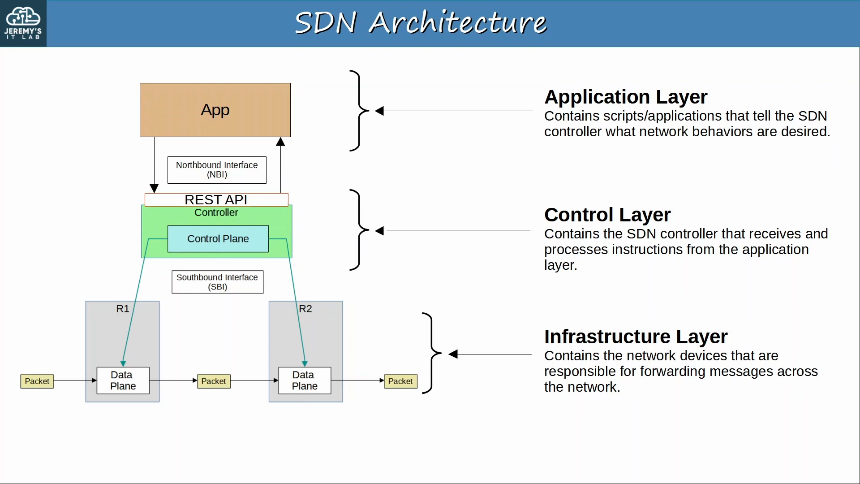
CRUD (Create, Read, Update, Delete) refers to the operations we perform using REST APIs.
- Create operations are used to create new variables and set their intial values.
- ie. create variable “ip_address” and set the value to “10.1.1.1”
- Read operations are used to retrieve the value of a variable.
- ie. what is the value of variable “ip_address”?
- Update operations are used to change the value of a variable.
- ie. change the value of variable “ip_address” to “10.2.3.4”
- Delete operations are used to delete variables.
- ie. delete variable “ip_address”
HTTP uses verbs (aka. methods) that map to these CRUD operations.
REST APIs typically use HTTP.
When an HTTP client sends a request to an HTTP server, the HTTP header includes information like this:
- An HTTP Verb (ie. GET)
- A URI (Uniform Resource Identifier), indicating the resource it is trying to access.
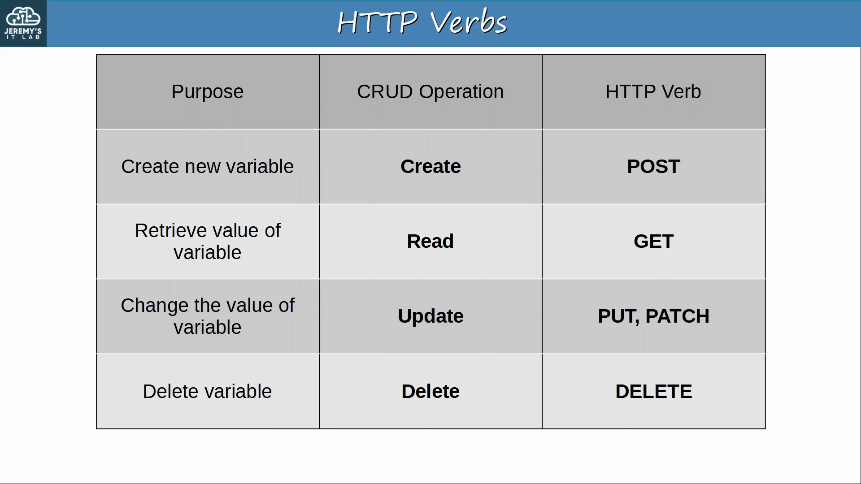
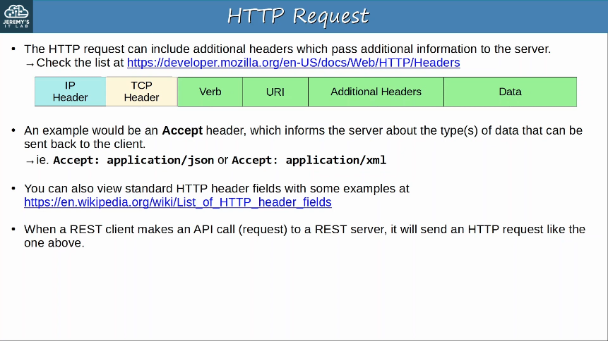
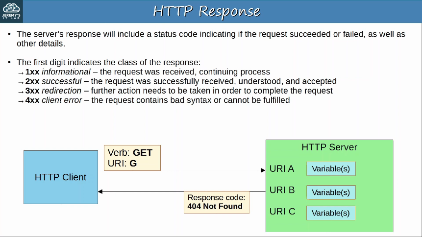
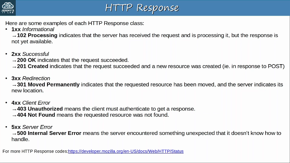
REST stands for Representational State Transfer.
REST APIs are also known as REST-based APIs or RESTful APIs.
- REST isn’t a specific API. Instead, it describes a set of rules about how the API should work.
The six constraints of RESTful architectures are:
- Uniform Interface
- Client-server
- Stateless
- Cacheable or non-cacheable
- Layered system
- Code-on-demand (optional)
REST APIs must support caching of data.
Caching refers to storing data for future use.
- For example, your computer might cache many elements of a web page so that it doesn’t have to retrieve the entire page every time you visit it.
- This improves performance for the client and reduces the load on the server
Not all resources have to be cacheable, but cacheable resources MUST be declared as cacheable.
6.6 Recognize the capabilities of configuration management mechanisms Puppet, Chef, and Ansible
Configuration management tools are network automation tools that facilitate the centralized control of large numbers of network devices.
These tools were originally developed after the rise of VMs, to enable server system admins to automate the process of creating, configuring, and removing VMs.
They are also widely used to manage network devices.
These tools can be used to perform tasks such as:
- Generate configurations for new devices on a large scale.
- Perform configuration changes on devices (all devices in your network, or a certain subset of devices)
- Check device configurations for compliance with defined standards.
- Compare configurations between devices, and between different version of configurations on the same device.
Ansible is a configuration management tool owned by Red Hat.
- Ansible itself is written in Python
- Configurations are stored on the Ansible server in playbooks that are written in YAML.
- Ansible is agentless
- it doesn’t require any special software to run on the managed devices
- Ansible uses SSH to connect to devices, make configuration changes, extract information, etc (TCP port 22)
- Ansible uses SSH to connect to devices, make configuration changes, extract information, etc.
- Ansible uses a push model. The ansible server (Control node) uses SSH to connect to managed devices and push configuration changes to them
- Puppet and Chef use a pull model
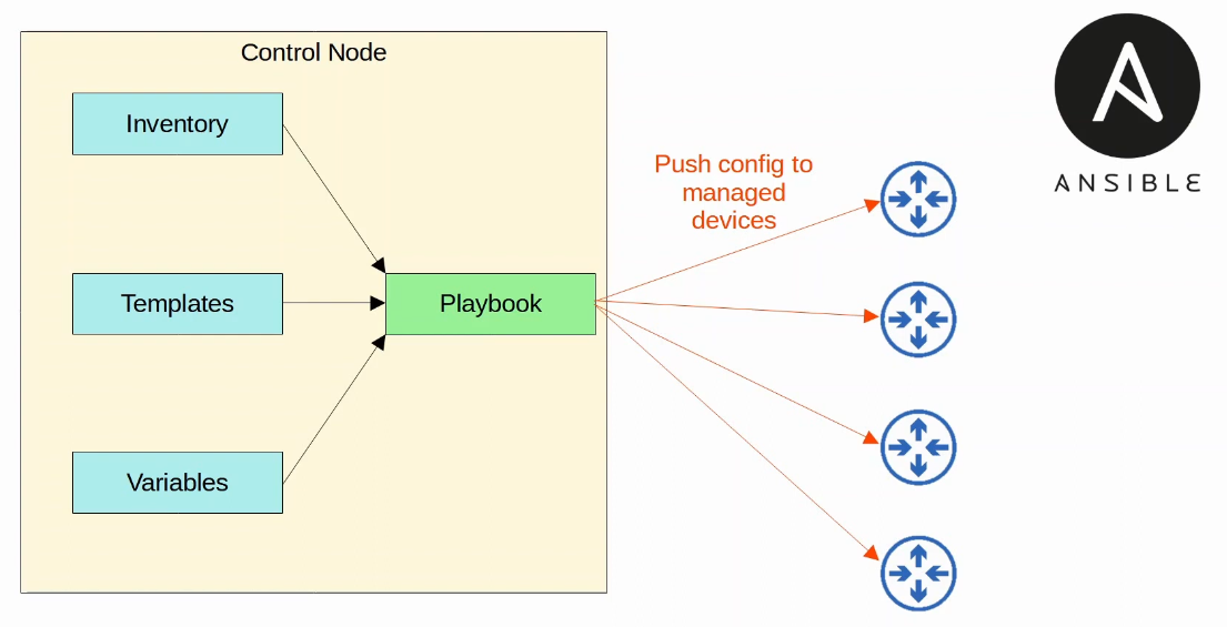
- After installing Ansible itself, you must create several text files:
- Playbooks
- These are files are ‘blueprints of automation tasks’. They outline the logic and actions of the tasks that Ansible should do. Written in YAML.
- Inventory
- These files list the devices that will be managed by Ansible, as well as characteristics of each device such as their device role (access switch, core switch, WAN router, firewall,etc). Written in INI, YAML, or other formats.
- Templates
- These files represent a device’s configuration file, but specific values for variables are not provided. Written in a Jinja2 format.
- Variables
- These files list variables and their values. These values are substituted into the templates to create complete configuration files. Written in YAML.
Puppet is a configuration mangement tool written in Ruby.
- uses a client/server architecture
- Puppet is typically agent-based
- Specific software must be installed on the managed devices.
- Not all Cisco devices support a Puppet agent.
- It can be run agentless, in which a proxy agent runs on an external host, and the proxy agent uses SSH to connect to the managed devices and communicate with them.
- The puppet server is called the ‘Puppet master’.
- Puppet uses a pull model (clients ‘pull’ configurations from the Puppet master).
- Clients use TCP 8140 to communicate with the Puppet master.
- Instead of YAML, it uses a proprietary language for files.
- Text files required on the Puppet master include:
- Manifest: This file defines the desired configuration state of a network device.
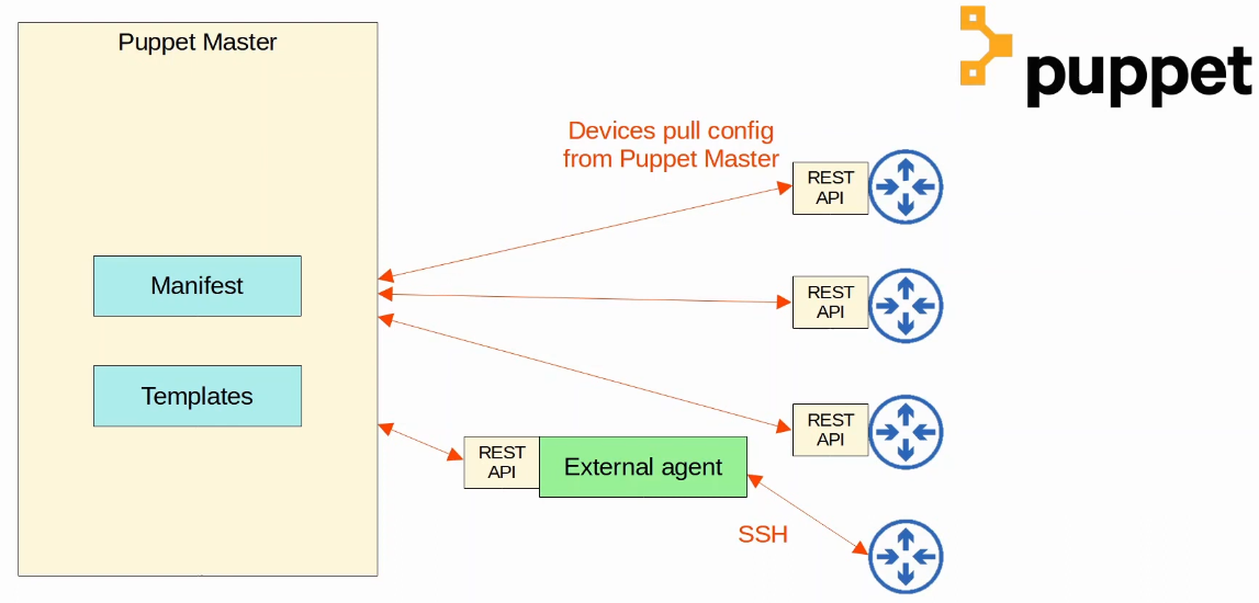
Chef is a configuration management tool written in Ruby.
- uses a client/cerver architecture, or a standalone client configuration
- Chef is agent-based
- Specific software must be installed on the managed devices.
- Not all Cisco devices support a Chef agent.
- Chef uses a pull model
- The server uses TCP 10002 to send configurations to clients
- Commincates by using HTTPS on the traditional TCP port 443.
- Files use a DSL (Domain-Sepcific Language) based on Ruby.
- Text files used by Chef include:
- Resources: The ‘ingredients’ in a recipe. Configuration objects managed by Chef.
- Recipes: The ‘recipes’ in a cookbook. Outline the logic and actions of the tasks performed on the resources.
- Cookbooks: A set of related recipes grouped together.
- Managed nodes that are running the Chef Client can pull cookbooks form the server. Standalone clients that do not have access to a server can run chef-solo and pull cookbooks from a local directory or from a tar.gz archive on the internet.
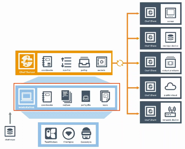
Ansible, Puppet, Chef comparison:
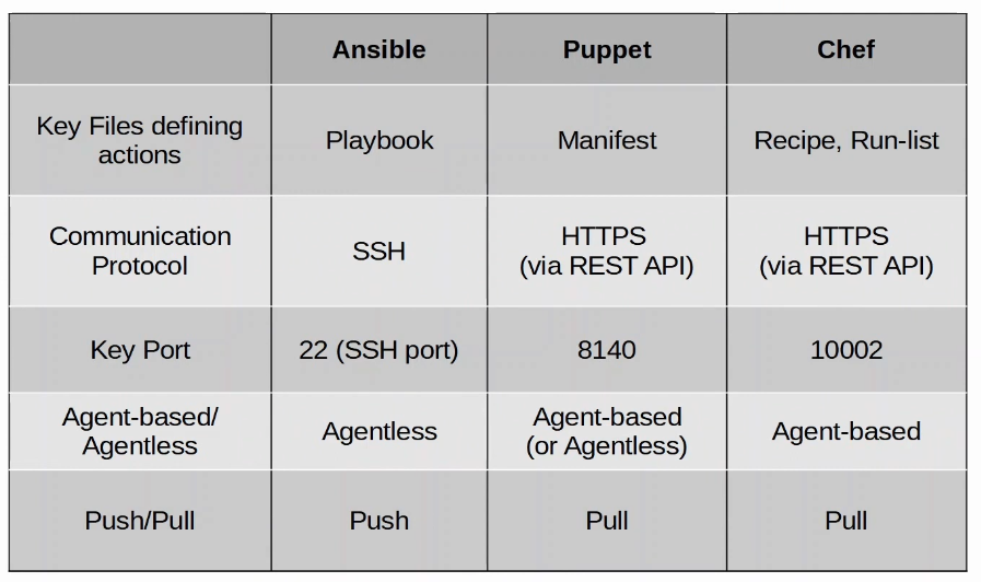
Puppet resource declaration example:
sudo::conf { ‘CoAdmins’ :
ensure => present,
content => ‘%admin ALL=(ALL) ALL’,
}
Chef recipe example:
sudo “CoAdmins”
group “CoAdmins”
nopasswd true
Python script that defines a python dictionary:
sudo = {
“group” : “CoAdmins”
“content” : “%admin ALL=(ALL) ALL”
}
JSON object example”
{
sudo : {

    "group" : "CoAdmins",

    "content" : "%admin ALL=(ALL) ALL"

}
}
6.7 Recognize components of JSON-encoded data
Data serialization is the process of converting data into standardized format/structure that can be stored (in a file) or transmitted (over a network) and recontructed later (ie. by a different application).
- This allows the data to be communicated between applications in a way both applications understand.
- Data serialization languages allow us to represent variable with text.
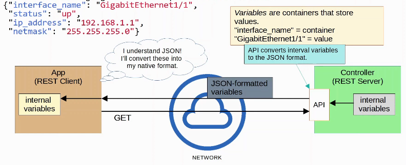
JSON (JavaScript Object Notation) is an open standard file format and data interchange format that uses human-readable text to store and transmit data objects.
It was derived from JavaScript, but it is languaage-independent and many modern programming languages are able to generate and read JSON data.
- REST APIs often use JSON.
Whitespace is insignificant.
JSON can represent four ‘primitive’ data types:
- string
- number
- boolean
- null
- a null value represents the intentional absence of any object value. It is not surrounded by quotes.
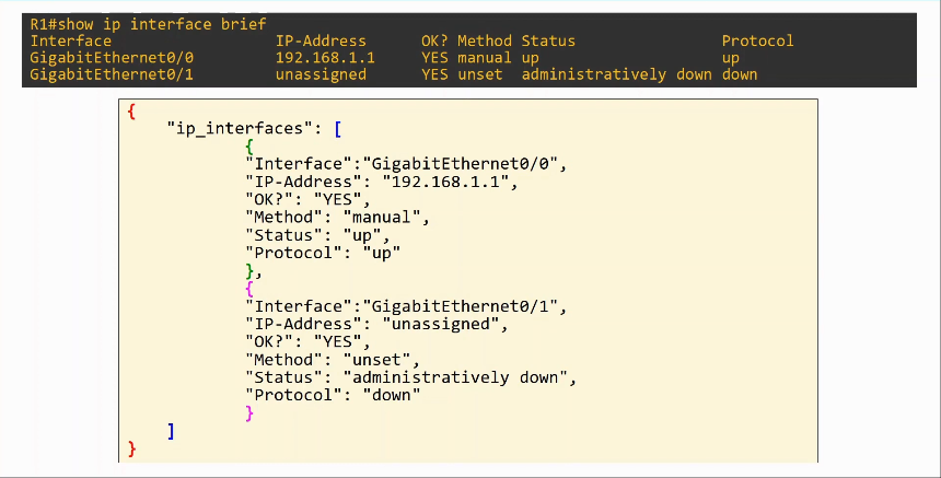
JSON also has two ‘structured’ data types:
- object
- An object is an unordered list of key-value pairs (variables)
- the key is a string
- the value is any valid JSON data type (string, number, boolean, null, object, array)
- The key and value are seperated by a colon.
- If there are multiple key-value pairs, each pair is seperated by a comma.
- inside curly brackets
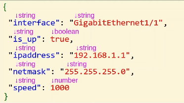
- array
- An array is a series of values seperated by commas, inside of square brackets
- not key-value pairs
- the values don’t have to be the same data type.
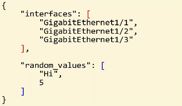
XML (Extensible Markup Language) was developed as a markup languaage, but is now used as a general data serialization language.
- markup languaages (ie. HTML) are used to format text (font, size, color headings, etc)
- Often used by REST APIs
YAML (YAML Ain’t Markup Language) is named to distinguish its purpose as a data-serialization languaage rather than a markup language.
YAML is used by the network automation tool Ansible.
YAML is very human-readable.
Whitespace is significant (unlike JSON and XML)
- Indentation is very important
Commands to know
Passwords
- username (user-name) password (password)
- configure a user name with a plain-text password.
- username (user-name) secret (password)
- configure a username with a password stored as an MD5 hash.
- username (user-name) secret 5 (hash-value)
- assigned MD5 hash value manually, instead of converting password
- 5 parameter indicates that the assigned value is already in MD5 hash form
PoE
- power inline police
- used in interface config mode, interface will enter an error-disabled state, effectively shutting down the port, when an attached PD attemps to draw more than the cutoff power from the configured interface. A log message describing the event will also be sent to the console.
- errdisable recovery cause inline-power
- used in global config mode to enable error-disable auto recovery for inline power, automatically resets port after auto recovery mechanism timer expires
- power inline police action log
- used in interface config mode, when an attached PD attempts to draw more than its allocated power from the interface, it will cause the port to restart, and a log message will appear on the console.
- with log action configured, restarts instead of becoming errdisabled
CDP
- show cdp neighbors
- shows device ID, local interface, holdtime, capability, platform and port ID.
- show cdp neighbors detail
- used in privilege exec mode (enable) to show detailed information about neighboring CDP devices
- includes: device, entry (IP) addresses, platform, interfaces, holdtime, version, advertisement, duplex, power drawn, power request id, power request levels, etc
STP
- spanning-tree portfast
- used in interface config mode for enabling PortFast on specific ports, used for edge ports such as access ports
- transitions the port into the STP forwarding state without going through the STP listening and learning states.
- if enabled on a port connected to a switch, the potential for creating STP loops increases greatly.
- spanning-tree portfast default
- enables PortFast for all access ports on a switch, global config mode
- spanning-tree guard root
- root guard is used to prevent newly introduced switches from being elected as the new root switches.
- allows adminstrator to maintain control over which switch is the root.
- When STP is used, the device with the lowest switch priority is elected the root. If a new device is added to the network with a lower priority than the current root, it will become the new root.
- This could cause the network to reconfigure in unintented ways.
- typically used on edge ports that have PortFast enabled
- portfast can cause switching loops if a new switch is connected to a portfast-enabled port, BPDU prevents this by placing the port in an error-disabled state and shuts down the port upon receiving the receipt of the BPDUs.
- the port must be manually re-enabled, or it can be recovered automatically by configuring the errdisable recovery cause bpduguard command and the errdisable recovery interval interval command.
- BPDU on portfast interfaces prevent a rogue switch from modifying STP topology.
- spanning-tree loopguard (default OR loop)
- loop guard feature prevents nondesignated ports from inadvertently forming bridging loops if the steady flow of BPDUs is interrupted.
-
default will enable loop guard for the entire switch in global config, loop will enable for specific ports in interface config mode.
- when port stops receiving BPDUs, loop guard puts the port into the loop-inconsistent state, which keeps the port in a blocking state.
- After the port starts receiving BPDUs again, loop guard automatically re-enables the port so that it transitions through the normal STP states.
DAI (Dynamic ARP Inspection)
- ip arp inspection vlan (number or range)
- used in global config mode (conf t)
- a range of VLANs can be entered by using a comma-seperated list or a dash range.
- configuring DAI on each VLAN ensures that traffic sent from each host is inspected (prevent ARP poisoning/spoofing)
- DAI is configured globally on a switch on all access, trunk, EtherChannel, and PVLAN ports for specified VLANs and cannot be configured on specific interfaces.
DTP
- switchport mode dynamic (auto or desirable)
- because a switch port in auto mode does not actively negotiate to operate in trunk mode, it will only form a trunk link if negotations are initiated by the neighboring interface
- a neighboring interface will initiate negotiations only if it is configured to operate in trunk mode or desirable mode.
- by contrast, a switch port in desirable mode will actively negotiate to operate in trunk mode and will form a trunk link with a neighboring port that is configured to operate in trunk, desirable, or auto mode.
- switchport mode trunk
- used to configure the port in trunk mode, and doesn’t engage in negotation over DTP, should be followed by switchport nonegotiate to accomplish this
- switchport mode access
- to configure the port in access mode and doesn’t use DTP.
- show interfaces fa0/0 trunk
- indicates the switchport mode configured for a particular interface
-
off - indicates that the port has been statically configured to operate in access mode
-
on - indicates that the port has been statically configured to operate in trunk mode
-
auto - indicates that the port will dynamically determine it’s operating mode; the port operates in access mode unless the neighboring interface actively negotiates to operate as a trunk
-
desirable - indicates that the port will dynamically determine its operating mode; the port operates in access mode unless it can actively negotiate a trunk connection with a neighboring interface
EtherChannel
- interface port-channel (number)
- used in global config mode
- specifies the port-channel interface to configure and enters the interface configuration mode, creates the channel group if it does not exist
- interface range (interface range)
- specifies the interface that you want to add to a channel group, and enters the interface configuration mode.
- channel-protocol (lacp or pagp)
- specifies the aggregation protocol used to negotiate the creation of the etherchannel (optional).
- EtherChannel must match one ach switch, or they will be unable to dynamically establish an EtherChannel link between them.
- In addition, if a protocol is explicity configured, each local switch port in the EtherChannel bundle must be configured to operate in a mode that is compatible with the channel protocol or the switch will display an error message and refuse to bundle the offending interface.
- channel-group (number) mode (on/active/passive {auto/desirable [non-silent]})
- used in interface range config
- number to specify particular channel group, should correspond to the PortChannel interface being configured
- the on keyword configures the channel group to unconditionally create the channel with no LACP or PAgP negotiation. In the on mode , a functional EtherChannel exists only if a channel group that is in the on mode is connected to another channel group that is also in the on mode.
- You can issue the command show etherchannel summary to verify the status of an EtherChannel link and to determine which aggregation protocol, if any, was used to establish the link.
- The auto, desirable, and non-silent keywords can only be used with PAgP.
- The desirable keyword configures the channel group to actively negotiate PAgP, and the auto keyword configures the channel group to listen for PAgP negotiation to be offered.
- Either or both sides of the link must be set to desirable to establish an EtherChannel over PAgP; setting both sides to auto will not establish an EtherChannel over PAgP.
- The optional non-silent keyword requires that a port receive PAgP packets before the port is added to the channel.
- The active and passive keywords can be used only with LACP. The active keyword configures the channel group to actively negotiate LACP, and the passive keyword configures the channel group to listen for LACP negotation to be offered. Either or both sides of the link must be set to active to establish an EtherChannel over LACP; settings both sides to passive will not establish an EtherChannel over LACP.
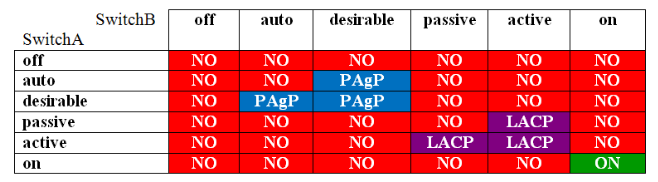
VLAN
- show vlan brief
- shows vlans, name, status ports
- vlan vlan-id
- enter VLAN config mode, and/or create a VLAN
- name name
- configure a name for the VLAN
- switchport access vlan vlan-id
- used in interface configuration mode, configures the interface into a specific VLAN, if the VLAN doesn’t exist, it will be created
- configures these ports to reside on VLAN 1 if the ports are operating access mode
- switchport mode access
- configures the ports to operate in access mode
- switchport trunk native vlan vlan-id
- configures the native VLAN of the switch, used in interface config mode
- default is VLAN 1
- ip arp inspection vlan (vlan-id OR vlan-range)
- ensures that traffic sent from each host on the VLAN is inspected
- in addition, a port is configured as an untrusted port when DAI is enabled on that port.
- ip arp inspection trust
VTP
- vtp mode (server, client, or transparent)
- used from global config mode or vlan config mode.
- by default, switches are configured for VTP server mode.
NAT
- show ip nat translations
- shows protocol, inside global IP, inside local IP, outside local IP, outside global IP
IPV4 static routes
- ip route (destination network ip address) (subnet mask) (next-hop ip address)
- ip route (destination network ip address) (subnet mask) (exit-interface)
- show ip route / show ipv6 route
-
Local host routes are marked with an L
- IPv4 addresses that are manually configured with a /32 mask are considered to be connected addresses and are marked wtih a C
- Routes that are marked with an O are OSPF routes
- Routes that are marked with D are EIGRP routes
- OSPF an EIGRP are considered network routes
- Routes that are marked with an S are static routes. Normal static routes have an AD of 1
- AD is the first number in the brackets, the second number is metric [AD/metric]
- A static route with a modified AD is called a floating static route and is often used as a backup route in case the primary route goes down.
- Routers marked with a (*) in the output are default routes. A static default route can be configured by issuing the ip route 0.0.0.0 0.0.0.0 (next-hop-IP OR interface) command.
-
S* 0.0.0.0 [1/0] indicates a static default route.
IPv6
- ipv6 enable
- used on interface config mode to enable IPv6 enable
- after issuing this command on an interface, it can use its automatically derived, link-local IPv6 address to communicate with other IPv6 enabled devices on directly connected networks.
- ipv6 address (ip address) (/prefix) [eui-64]
- used on interface config to manually assign an IPv6 address. eui-64 keyword configures a static IPv6 prefix but allows the router to automatically generate a 64-bit interface ID known as EUI-64 interface ID based on the interface’s MAC address.
- ipv6 address autoconfig
- configures an interface to automatically assign itself a global unicast IPv6 address using SLAAC.
- SLAAC configurations occur based on information that is sent in router advertisements from an IPv6 gateway operating on the same network segment.
- also enables the interface to obtain additional information from a DHCPv6 server if a DHCPv6 server exists on the network as is configured to send nonaddress information,
- ipv6 address dhcp
- configures a DHCPv6 client interface to use stateful DHCPv6 addressing, which configures addressing information and extra information from the DHCPv6 server8.
- ipv6 route (destination network IP address /#subnet) (outboundinterface 0/0) (next-hop IPv6 address)
- configures fully specified static route in which the destination network, outbound interface, and next-hop IPv6 address are all configured directly.
- ex: ipv6 route 2001:db8:a::/32 fastethernet 0/1 2001:db8:b::1
- fully specified static routes are most often used when the outbound interface is multiaccess and could therefore be confgured with multiple next-hop addresses. The next-hop address that is specified in the command must be directly connected to the outbound interface.
- ipv6 route (destination network IP address /#subnet) (outboundinterface 0/0)
- configures a directly attached static route
- ex: ipv6 route 2001:db8:a::/32 fastethernet 0/1
- when a directly connected static route is configured, the router assumes that any packet that matches the destination network is reachable throuh the specified outbound interface. Therefore, the packet’s fll destination address is used as the IPv6 next-hop address.
- ipv6 route (destination network ip address /#subnet) (next-hop IP address)
- configures a recursive static route
- ex. ipv6 route 2001:db8:a::/32 2001:db8:a::1
- in this example, the command configures the routter to resolve all IPv6 addresses in the 2001:db8:a::/32 prefix through the next hop that has been assigned the IPv6 address of 2001:db8:a::1.
- the router assumes the outbound interface to be the interface to which the next hop is either directly or indirectly connected. In other words, the next-hop IPv6 address must be resolvable through the outbound interface.
- ipv6 route (destination network ip address /#subnet) (next-hop IP address) (administrative distance #)
- will configure a floating static route with an AD of 5.
ACL
- access-class (number) (in/out)
- used in line config mode (enabled by line vt # #)
- in/out configured inbound or outbound
- configures VTY lines #-# to apply ACL # in the in/out direction
- access-list (number) (deny/permit) (source IP address [source-wildcard] OR host ip address OR any)
- examples: access-list 55 permit 172.18.0.12 0.0.0.0
- access-list 55 deny any
- creates a standard ACL, place as close to the destination as possible.
- standard when ACL number is 1-99 or 1300-1999
- extended access-list command
- can permit or deny packets based on source IP address, destination IP address, protocol, and port.
- place close as possible to the source of traffic
- extended when ACL number is 100-199 or 2000-2699
- ip access-list standard (name)
- configure a standard ACL by name instead of number
- places the device in standard ACL config mode, where you can issue multiple commands to configure the named ACL.
- to create these ACL statements, use the command: [sequence-number] (deny or permit) (host ip address OR source IP address source wildcard OR any) where sequence number is an optional number that indicates the ACL statemens will be evaluated.
- If you do not issue a sequence number, the statements will be processed in the order which they are issued.
- ip access-list extended (name)
- configured an extended ACL by name instead of number
- places the device in extended ACL configuration mode, where you can issue [sequence-number] (deny or permit) protocol (source IP source wildcard) [operator port] (destination IP destination-wildcard) [operator port]
- where sequence number is a optional number that indicates the order which the ACL statements will be evaluated.
- show access-lists
- shows configured standard and extended ACLs
DHCP
- ip dhcp pool (name/number)
- used in global config mode to create dhcp pool
- network (ip-address) (subnet mask or /prefix)
- used in DHCP pool config mode, the router will provide IP addresses to hosts connected to the router interface that belongs to that subnet.
- host (ip address) (subnet mask or /prefix)
- used in DHCP pool config mode, used to configure an IP address for manual binding. Manual binding enables a device to always receive the same IP address from DHCP by associating a static IP address with the device’s MAC address.
- after using the host command, you should issue the following command:
- client-identifier (MAC address)
- Statically maps this device to the IP address defined in host
- you cannot use the same DHCP pool for manual bindings and for dynamic IP address allocation.
- ip address dhcp
- configures an interface to become a DHCP client so that it can receive IP configuration information from a DHCP server. A DHCP client can receive an IP address, a subnet mask, a domain name, a DNS server, and more from a DHCP server.
OSPF
- router ospf process-id
- enables OSPF router configuration mode, used in configured terminal mode
- router-id ip-address
- manually configures router-id, used in router config mode
- if router ID is not manually configured, the router ID will be the highest Loopback IP address configured on a router. if a loopback IP address is not configured, then the router ID will be the highest IP address among the configured interfaces.
- show ip ospf interface brief
- shows interfaces, PID, Area, IP address/mask, cost, state. Full adjacencies/total count of neighbors
-
show ip ospf neighbor
- show ip ospf int g0/0
- shows state, priority, DR+BDR router IDs and interface IP addresses, neighbor count, (full) adjacent neighbor count
- network (address mask) area (area-id)
- configure an OSPF area in OSPF router configuration mode
- ip ospf priority (#1-255)
- used in interface config mode, configures interface priority in order to manually configure DR/BDR (default is 1)
- if set to 0, the router can not become the DR/BDR for the subnet
- once DR/BDR is set they will keep their role until OSPF is reset using clear ip ospf process
- When the DR goes down, the BDR becomes the new DR. Then an election is held for next BDR.
- ip ospf network (broadcast OR non-broadcast OR point-to-multipoint [nonbroadcast] OR point-to-point)
- configures network type on an OSPF interface
- if not issued, the default OSPF network type depends on the type of network which the interface is connected
- OSPF broadcast network type is enabled by default on Fiber (FDDI) and Ethernet interfaces.
- Multicast updates are sent, manual config of neighbor routers is not required. Hello timer 10s, dead timer 40s
- DR and BDR elections are performed
- OSPF nonbroadcast network type is enabled by default on Frame Relay and X.25 interfaces.
- nonbroadcast do not allow multicast, so manual configuration of neighbor routers with neighbor command is required so that OSPF sends unicast updates. Hello timer 30s, dead timer 120s
- DR and BDR elections are performed
- OSPF point-to-point network type is enabled by default on HDLC and PPP (Point-to-point protocol) serial interfaces.
- multicast updates are sent, so manual configuration of neighbor routers is not required. Hello timer 10s, dead timer 40s
- DR and BDR elections are not performed
- OSPF point-to-multipoint network type
- Multicast updates are sent, so manual configuration of neighbor routers is not required. Hello timer 30s, dead timer 120s
- DR and BDR elections are not performed
- OSPF point-to-multipoint nonbroadcast network type
- Nonbroadcast networks do not allow multicasts; so manual configuration of neighbor routers with neighbor command is required so that OSPF sends unicast updates. Hello timer 30s, deadtimer 120s.
- DR and BDR elections are not performed
- router id (value)
- manually configure an OSPF router ID in OSPF router configuration mode.
- an OSPF router will always select a manually configured router ID over any interface IP addresses.
- distance (new AD value)
- configures the AD of routing protocols in router configuration mode
- for ex. to change the AD of OSPF from 110 to 80, you should issue the following commands:
- #router ospf 1
- #distance 80
- neighbor (IP address of neighbor) (priority number) (poll-interval seconds) (cost number) [database-filter all]
- allows for manual configuration of neighbor routes
- not needed on broadcast networks
- priority number indicates route priority value of nonbroadcast neighbo associated with the IP address specified. default is 0. doesn’t apply to point-to-multipoint interfaces
- poll interval represen poll interval time in seconds, should be much longer than hello interval. default is 120 seconds. doesn’t apply to p-t-mp interfaces
- cost aassigned cost to neighbor, neighbors will no specific cost configured will assumed cost of interface, based on ip ospf cost command. does not apply to nonbroadcast multiaccess (NBMA) networks
- database-filter all filters outgoing LSAs to an OSPF neighbor
- maximum-paths maximum number
- Many OSPF routers can insert a maximum of four equal-cost paths into the routing table by default. You can override the default maximum by issuing the maximum-paths maximum command in OSPF router configuration mode, where maximum indicates the maximum number of equal-cost paths to insert into the routing table.
- ip ospf hello-interval seconds
- used in interface config mode, manually configures hello timer interval (default 10 seconds on point-to-point and broadcast links, 30 seconds on NBMA links)
- ip ospf dead-interval seconds
- used in interface config mode, manually configures dead timer interval (default 4x hello timer)
- default-information originate
- configures an OSPF router to inject its default route into OSPF as an external route, thereby advertising its default route to neighboring routers.
SSH (Secure Shell)
- device must be running a K9 IOS image
- to enable SSH for VTY lines on a Cisco router, complete the following:
- configure the router with a host name other than Router by issuing the hostname command
- configure the router with a domain name by issuing the ip domain-name command
- generate an RSA key pair for the router by issuing the crypto key generate rsa command.
- configure the VTY lines to use SSH by issuing the transport input ssh command from line configuration mode.
- the crypto key generate rsa command will automatically enable SSH on a router.
- creates a set of RSA keys that can be used for SSH sessions.
- the transport input ssh command does not enable SSH on the router. This command only configures the VTY lines to use SSH if SSH has already been configured.
- the crypto key zeroize rsa command removes RS keys from a router. You may want to remove RSA keys in order to generate new keys.
- the enable secret command can be used to help prevent unauthorized access to priveged EXEC mode. Using this command is more secure than enable password because the password is stored in MD5 hash instead of plain text.
- the no transport input telnet command can be used to prevent Telnet access to a router. Telnet is sent unencrypted as plain text, so it is not as secure as SSH. Using this will ensure that remote management connections to the router are encrypted.
NTP (Network Time Protocol)
- ntp server ip-address
- enables NTP static client mode on router, used in global config mode
- Static client receives its time from an NTP server where ip-address is the IP address of the NTP server that the client will use to receive it’s time
- ntp broadcast client
- enables NTP broadcast client mode on router, used in interface configuration mode.
- An NTP broadcast client listens on the configured interface for NTP broadcasts from an NTP server, which the NTP client uses to adjust its time.
- The different between a broadcast client and a static client is that a broadcast client can receive its time from any NTP server. By contrast, a static client receives its time from the NTP server specified in the ntp server command
- ntp authenticate
- enables NTP authentication on router, used in global config mode.
- Authentication can be used with NTP to provide source verification for NTP synchronization.
- NTP authentication supports only Message Digest 5 (MD5) keys.
- To enable authentication on an NTP client, you must issue the following command set:
- ntp authenticate
- ntp authentication-key key-number md5 key
- ntp trusted-key key-number
- ntp server ip-address key key-number
- To enable authentication on an NTP server, you should issue the following command set:
- ntp authenticate
- ntp authentication-key key-number md5 key
- ntp master stratum
- enables NTP server mode on router, used in global configuration mode, where stratum is an NTP stratum value from 1-15.
- If the stratum value is not specified, the NTP server uses the default stratum value of 8.
- NTP servers not only synchronize time with NTP clients but also with eachother.
- Devices with higher stratum numbers receive time from devices with lower stratum numbers.
- ntp peer ip-address
- enables NTP symmetric active mode on router, used in global config mode, where ip-address is the IP address of the NTP host.
- A device in symmetric active mode attemps to mutually synchronize with another NTP host; the host might synchronize the peer, or it might be synchronized by the peer.
WLC (Wireless LAN Controller)
- show ap config global
- displays global Sylog server settings for every AP that is joined to the Cisco WLC. The following is sample output from the show ap global command:
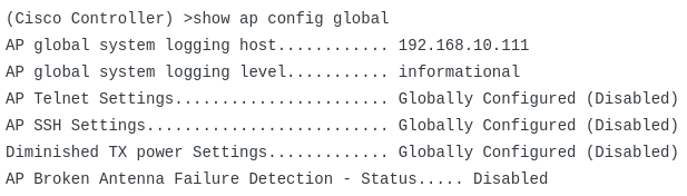
- show ap config general MyLAP
- displays IP addressing and other information about a Cisco access point named MyLAP. Similar to a Cisco wired router or switch, you can administer a Cisco AP or WLC by using a CLI. However, the CLI interface does not support the same Cisco IOS command set as a Cisco router or switch. You can configure a Cisco WLC or a Cisco AP either by using the built-in GUI in a browser or by using the CLI.
- show ap config general cisco-ap
- where cisco-ap is the host name of the Cisco AP that is configured with the information you want to display, produces general AP configuration output.
- This output includes information such as the AP’s IP address, the default gateway IP address, and the DNS server address. In addition, the output includes the subnet mask that is configured on the AP. Sample output from a Cisco AP:
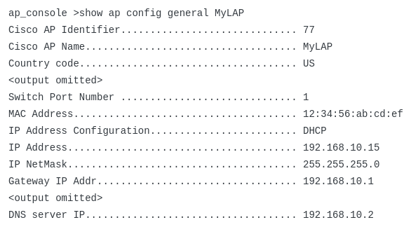
- The show ap core-dump MyLAP command displays the memory dump for the AP named MyLAP. The show ap core-dump cisco-ap command displays the memory core dump for the lightweight AP that is specified as the cisco-ap parameter. Core memory dumps can be large and are typically used for troubleshooting purposes when hardware failures occur.
- The show ap crash-file command displays a list of crash dump files and radio core dump files that have been generated by lightweight APs. This command is useful if you need to review the output of a crash file or core dump file for a specific AP.
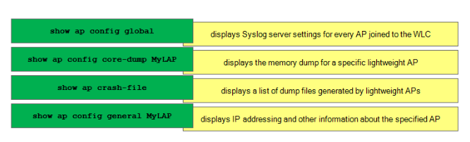
Port Security
- switchport port-security
- enables port security for a maximum of one MAC address
- switchport port-security maximum (#)
- used in interface config mode, configures the switch port to allow no more than two device, each with a unique MAC address, to send traffic into the port
- switchport port-security mac-address MAC Address
- used in interface config mode to statically configure a switch port to allow traffic from a specific MAC address
- Any MAC addressed that are not configured statically will be learned dynamically from incoming traffic, up to the maximum number of MAC addresses.
- switchport port-security mac-address sticky
- converts dynamically learned MAC addresses to sticky MAC addresses
- stick MAC addresses are stored in the running configuration
- to ensure that sticky MAC addresses are not lost during reboot, you should use write memory or copy running-config startup-config


 Insert a caption by placing italicised text immediately underneath the image, with no empty line in between.